16
WAAS GUS Signal Generator User Guide Rev 1
Chapter 2
Minimum Connections
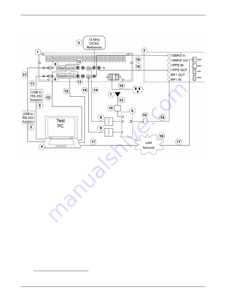
displays how you might typically set up the Signal Generator to test the signal.
Figure 4: Signal Generator Setup Example
Reference
Description
1
WAAS GUS Signal Generator (NovAtel P/N 1020347)
2
WAAS G-III Receiver (NovAtel P/N 01018740)
3
10 MHz Low Noise OCXO Reference Oscillator
4
Personal Computer (PC)
5
Off-the-Shelf USB to RS-232 Adapter
6
Data Source Module (NovAtel P/N 01020346)
7
Externally Powered GPS Antenna
8
50 Ohm 3:1 RF Combiner, SMA
9
50 dB SMA Coaxial Attenuators, 50 ohm
10
SMA Coaxial DC-block (the WAAS G-III Receiver RF1 In outputs DC power by default)
11
DB-9 Serial Cable
12
USB Cable Type-A to micro-USB (NovAtel P/N 60723119)
13
50 ohm Coaxial Cable, Male TNC to Male SMA (NovAtel P/N 60423064)
14
50 ohm Coaxial Cable, Male Type-N TNC to Male SMA
15
120 VAC Power Cable (NovAtel P/N 60723070)
16
50 ohm Coaxial Cable, Male TNC to Male TNC
17
CAT-5 Ethernet Cable
18
Local Area Network
19
Gain Element (either an amplifier or an attenuator)
1
1. To guarantee the noise power is between -152 dBm/Hz and -132 dBm/Hz at the input to the receiver.
The normal tracking range of the receiver is for CNos between 30 dB/Hz and 60 dB/Hz.


