background image


C-Series IM 1 MAY 2014 

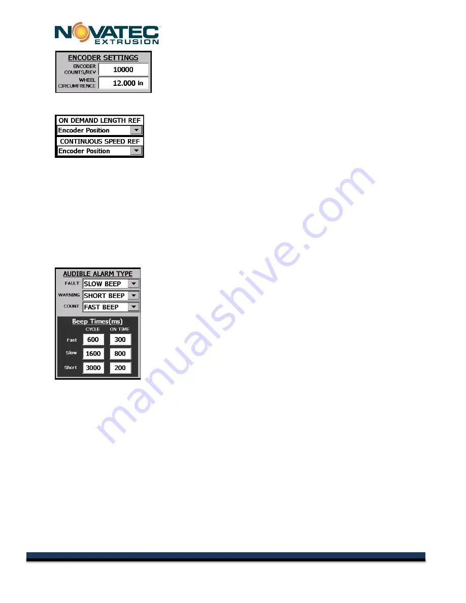
ENCODER SETTINGS 
Encoder Counts/Rev 

– The number of quadrature pulses per revolution 

of the encoder.  (If it is 2,500 ppr quadrature then the value is 10,000) 

Wheel Circumference – 

Distance for one revolution of the encoder, 

typically the circumference around wheel connected to encoder.   If the encoder is measuring 
slightly off, change this value to correct. 

ON DEMAND LENGTH REFERENCE

 – Choose the measuring method 

that the system will use to activate the cut sequence when using encoder 
mode. 

None

 – The length is calculated based on the Estimated Line Speed 

entered by the operator in the recipe.  This is useful for setup or when the 

customer wishes to enter the puller speed manually. 

Encoder

 – The encoder input pulses are used to determine the length. 

ProfiNet

 – An Ethernet connection between a Novatec supplied puller and the cutter is required.   

The puller transmits its actual speed every 1/10 seconds and the cutter uses this to calculate the 
accumulated length.  It calculates the point between the 1/10 second data by assuming the last 
received speed to get very accurate cuts. 

CONTINUOUS SPEED REFERENCE

 – This has the same options as the length reference but is 

used to determine the speed reference when running in continuous.  It is possible to use different 
modes for each depending on how stable a signal is.  The signals should be nearly identical or 
unpredictable switching might occur when changing between On Demand and Continuous modes. 
 

AUDIBLE ALARM TYPE


This is used to configure the horn sounds.  Different sounds can be set for 
Fault, Warning, and when the Count gets to set values.  the choices are 
None, Slow Beep, Short Beep, Fast Beep, and Continuous.  Each beep 
duration and cycle time can be customized so that operators can distinguish 
between machines audibly. 


31 

© 2015 NOVATEC Inc. All Rights Reserved 

Document: C-Series 7 MAY 2015 

Содержание Bessemer C Series

Страница 1: ...Rotary Knife Cutter Model Bessemer C Series C 2 C 3 C 4 NOVATEC INC 2015 All Rights Reserved C Series IM 12 MAY 2015 ...

Страница 2: ...IM 12 MAY 2015 Model ___________________________ Serial ____________________________ DISCLAIMER NOVATEC Inc shall not be liable for errors contained in this Instruction Manual nor for misinterpretation of information contained herein NOVATEC shall not in any event be held liable for any special indirect or consequential damages in connection with performance or use of this information 2015 NOVATEC...

Страница 3: ...wer Loss 15 10 0 SCREEN CONVENTIONS AND COMMON ELEMENT 15 10 3 Screen Title 16 10 4 Machine Status 16 10 5 Standard Navigation Buttons 16 10 6 Cut Start Stop Buttons 16 11 0 SYSTEM STARTUP 17 11 1 Initial Screen 17 11 2 POWER UP Screen 17 11 2 1 Verify Safety Reset System 17 11 2 2 Verify Safety Press E Stop 18 11 2 3 Reset System to Home Screen 18 11 2 4 Homing Screen 18 12 0 MACHINE OPERATION 19...

Страница 4: ... 1 29 13 6 SETUP Screen 2 30 13 7 SETUP Screen 3 32 13 8 Servo Setup Page 34 13 9 Batch Counter Screens 36 14 0 MAINTENANCE 37 At Startup 37 Every bushing or blade change 37 Daily 37 Every 3 Months 37 15 0 WARRANTY NOVATEC INC EFFECTIVE DATE 6 12 2012 38 2 2015 NOVATEC Inc All Rights Reserved Document C Series 7 MAY 2015 ...

Страница 5: ...ry equipment Explanation of Symbols This manual includes both general and task specific safety precautions These precautions are highlighted in the manual by the following categories WARNING This symbol identifies situations that are potentially hazardous to personnel or equipment NOTE Highlights information provided in text or procedures This information may or may not be related to safety 3 2015...

Страница 6: ...onds of E Stop It also is monitoring itself for Safe Standstill which is interlocked to the guard lock With the addition of redundant safety relays motor contactor and guard interlock the system can exceed SIL 3 PL d safety requirements for a Cat3 safety hazard NOTE Additional guarding may be required where the product enters and exits the bushing NOTE The Safety Circuit Must Be Tested on 90 Hour ...

Страница 7: ...g lubricant chip collection reservoir through a felt blade wipe to clean the blade and then through the bushings again to make another cut The cut extrudate continues to move through the bushing where it is either collected or is conveyed further downstream by an optional conveyor Two cutting modes are available ON DEMAND cutting mode and CONTINUOUS cutting mode Within these two major modes of ope...

Страница 8: ...with 12 circumference measuring wheel Knife thicknesses of 015 020 025 030 040 available Blades shaped and sharpened to meet custom application requirements Safety interlocks provided for operator safety Removable cutting chamber cover with integral reservoir provides full access to cutting chamber and cutting fluid reservoir Split clamp bushing arrangement provides easy bushing setup Indicator li...

Страница 9: ...to start the next cut and the next cut will be ignored resulting in a part that is twice as long as intended It is also possible to set the On Demand Blade Speed and the Required CPM so high that eventually it faults the drive because there is too much power required for the move Below are charts that show the blade speed versus CPM for several cutters It was determined by shop testing Actual resu...

Страница 10: ...C Series IM 1 MAY 2014 8 2015 NOVATEC Inc All Rights Reserved Document C Series 7 MAY 2015 ...

Страница 11: ...line speed 7 0 INSTALLATION 1 Carefully unpack the cutter and any other components delivered with it Check all packaging for loose parts documentation and other included items Carefully inspect the cutter Ensure that no wires bolts screws terminals or other connections have come loose during shipping Check to ensure that all moving parts are not obstructed by debris or excess packing material 2 Yo...

Страница 12: ...d injury Wait until the knife assembly fully stops before opening the inspection door Ensure the cutter has stopped rotating rotate the key switch clockwise to 2 o clock and wait 5 seconds for the door to unlock open the bushing guard yellow cover Rotate the cutter head to a point where the hole in the Cutter head lines up with a hole in the cutter enclosure Insert an Allen wrench through the two ...

Страница 13: ...ten the bushing holder inspect the blade clearance an additional time and make sure the cutter head can rotate a full revolution while clearing the bushings During initial set up the cylindrical bushing holders should be adjusted relative to one another by loosening the socket head cap screws on the front of the machine that clamp the bushing holders in place This adjustment ensures the rectangula...

Страница 14: ...hould be grounded at one end only and is typically grounded in the main I O enclosure WARNING Do not install communication cable where it will come into contact with any buildup of electrical charge It may be tempting to run the wire next to the material conveying lines but a substantial buildup of electrical charge can and will occur especially with certain types of plastic resins and if the conv...

Страница 15: ...m to all applicable national and local regulations When ready turn on the main disconnect Make sure that the E Stop button is in the out position Press the reset button KNIFE GUARD LOCK UNLOCK EMERGENCY STOP RESET EMERGENCY STOP ALARM LIGHT 13 2015 NOVATEC Inc All Rights Reserved Document C Series 7 MAY 2015 ...

Страница 16: ...e is a condition that requires operator attention The machine will continue to run Flashing Orange Blade is Homing The safety circuit has been powered on and the blade servo is homing Flashing Green Cutter is Ready The system is ready to start but is not running Press the Run Product or Run Scrap button to start machine Solid Green Cutter is Running Production The system is cutting production part...

Страница 17: ...h has an operation will appear raised by the use of shadowing around it to form a border If the border is grey then the current user logged on does not have access to activate the operation If the operator presses a button with a grey border a popup screen will appear prompting them to enter a user name and password When a button is pressed the shadowing on the border will change to indicate to th...

Страница 18: ...switch between any modes including between continuous and on demand cutting The Cut Scrap button may be hidden in the system setup TEST CUT Press this button to activate a single on demand test cut The test cut can be executed while the system is running on demand product It will not be counted and the following cut will be cut at the proper length time If the cut is done very close to when the se...

Страница 19: ...ed at by maintenance 11 2 POWER UP Screen This screen instructs the operator in the procedure to verify that the safety system is functioning properly The operator must first satisfy all of the conditions of the safety circuit The first 4 lines of the screen prompt instruct the operator on the procedure 11 2 1 Verify Safety Reset System Screen This screen appears and instructs the operator in the ...

Страница 20: ... is a true emergency 11 2 3 Reset System to Home Screen The prompt in the top left corner now instructs the operator to Reset the System again by twisting the Red Emergency Stop button clockwise AND pressing the Black RESET button again 11 2 4 Homing Screen Homing The prompt in the top left corner now indicates that the system is Homing The light will blink orange again When complete the screen wi...

Страница 21: ...e set on the recipe screen It will always show the product cut values when the system is stopped Blade Speed Enter the optimum blade speed for the cut when running in On Demand mode In Continuous Mode this is greyed out and shows the currently running blade speed that is determined by the calculation of Set Length and Line Speed Measured Length This is the length of the cut measured by the encoder...

Страница 22: ...e very close to when the set on demand cut needs to execute it may interrupt that cut A text cut cannot be executed while the unit is running in continuous The method for executing a text cut can be set in two ways in the system setup It can be set so that a popup menu shows up to confirm the test cut or it can be set so that the button must be held for 1 2 second before the test cut is executed T...

Страница 23: ... recipe This will return you to the Quick Ops screen and the loaded recipe number will appear on the Quick Ops screen NOTE Recipe Save As Screen The Recipe Save As screen is the same as the Recipe Select except that the Load Default Values is replaced by the check box Select the recipe that you want to save as and press the check box Now that a recipe number is entered you can press the EDIT RECIP...

Страница 24: ...ll distances Time Press the button to change to a cut that is activated by a repeating internal timer that is accurate to 1 millisecond Cycle Time Set the time from the start of one cut cycle to the start of the next cut cycle Level 2 or above personnel can use the SAVE button to save the recipe If there is a change to the running recipe from what is currently saved it will appear blue and pressin...

Страница 25: ... bad part and removes it from a box and is especially useful in high speed lines where editing the part count while running is nearly impossible Batch Counter Setup Access This button located under the Test Cut button is used to open a screen which contains all of the batch count features See Batch Count Screen Can also be accessed through the HOME screen 12 7 Production Metrics This box is on the...

Страница 26: ...ditions and user setup selections This is the view when the user is logged on as level1 authority but there is an alarm that has caused the system to shut down If the alarm horn is enabled the red Silence Alarm button appears in the middle of the screen notice that the Cut buttons are grey because they are no longer functional The alarm button also changed colors to indicate a problem This is the ...

Страница 27: ...ead of Set Length in inches This is the parameter that controls when the cut cycle is activated and is dependent on the operation mode When stopped it always shows the mode that is set for cutting product The modes can be changed on the recipe screen This view shows the machine running continuous mode which is a special encoder mode of operation This mode is automatically activated when the cut le...

Страница 28: ... proper level of password protection has not been entered prior to attempting changes the alpha numeric password entry keypad will appear prompting the user to input the proper user name and password before changes can be made User name and Password factory defaults level1 1111 Operator level2 2222 Production Supervisor level3 3333 Maintenance setup 4444 Factory Presets Setup Group Enter 3333 then...

Страница 29: ...n Has the same function as on the Quick Ops page See 13 9 page 33 Cutter Picture Shows the picture and model number for this cutter If the picture is blank there was a problem with the servo and PLC communicating Try cycling power Contact maintenance if the problem persists Installed Software Version This is important to note when contacting NOVATEC service Time Date If time and date are not corre...

Страница 30: ... some items in the recipe that can be changed by the level 1 operator and others require a level 2 operator but all items are visible to both See Current Recipe Screen Save Recipe The next button that looks like a floppy disc is used to save the recipe It is visible to level 2 and higher operators If the recipe hasn t changed it will appear grey and will not function If there is a change to the ru...

Страница 31: ... the Counter Screen PRODUCTION OUTPUTS 1 There are two dry contact outputs supplied in the control panel Q0 0 corresponds to Production Output 2 and Q0 1 corresponds to Production Output 1 They can be configured to trigger on many events including Part Cut Box Change Production Done Running Run Product Run Scrap Stopped or Faulted The signal can be delayed and held for a user settable amount of ti...

Страница 32: ...e end user must install their own device BUSHING SENSOR INSTALLED Press this to enable bushing sensors if they are installed Sensors are not installed on systems that have permanently installed bushings TEST CUT CONFIRM REQUIRED This button toggles the requirement for the popup window to confirm a test cut To avoid accidental activation the test cut button will require it be held for 1 2 second WE...

Страница 33: ...puller and the cutter is required The puller transmits its actual speed every 1 10 seconds and the cutter uses this to calculate the accumulated length It calculates the point between the 1 10 second data by assuming the last received speed to get very accurate cuts CONTINUOUS SPEED REFERENCE This has the same options as the length reference but is used to determine the speed reference when runnin...

Страница 34: ...n continuous mode Typically this is set to a value which can still give a good cut to the product Max On Demand Blade Speed This sets the maximum blade speed for On Demand cutting This will be limited by the max motor speed and is typically set by NOVATEC so that the drive does not fault when accelerating and decelerating and the overall system can handle the forces of the blade motion Note It is ...

Страница 35: ...will show the new background color When the color is ok press the checkbox to change the background colors of all the screens Black 0 0 0 is the default background color Care should be taken to not use very bright colors or colors that match other fields because they will bleach out some items RESET SYSTEM TO FACTORY DEFAULTS Pressing this button will set all of the setup values to the defaults fo...

Страница 36: ...odule control unit program and CF card The safety license is stored on the CF card If it is missing an alarm warning will be displayed but the system is still operational Motor Direction The motor direction is set when the machine is first commissioned based on the hardware used It is dependent on the machine being fed from the left side or right side Home Offset When the machine is first powered ...

Страница 37: ... is completely through the product USE DYNAMIC TUNING Dynamic tuning is used to change tuning parameters when running between on line and continuous On Demand operation requires an extremely fast response with large acceleration torques being used Continuous mode prefers a slower response to maintain the set speed in a tighter tolerance The values shown in the window can be adjusted to account for...

Страница 38: ... or Both The Warning Alarm will active a warning message the same way as any other The Alarm Siren activates the horn only which can be silenced on the Quick Ops Screen The siren must be configured in the system set up to activate At End of Box Requires box count to be enabled Used to determine the action of the cutter when the part count has reached the end of box At End of Production Used to det...

Страница 39: ...nclosure will be hotter than the air inside especially the servomotor and resistor Do not disable or bypass equipment safety features Refer to system component manuals for additional information WARNING Before beginning repair work disconnect all power sources and secure against inadvertent reconnection WARNING Auxiliary equipment may contain moving parts that may cut crush or otherwise injure per...

Страница 40: ...acturer and then only to the extent that NOVATEC is able to enforce such warranty or guaranty NOVATEC Inc has not authorized anyone to make any warranty or representation other than the warranty contained here Non payment of invoice beyond 90 days will invalidate the warranty A renewed warranty can be purchased directly from NOVATEC Please note that we always strive to satisfy our customers in wha...

Отзывы: