LED Display Controller Thunderview_S1
User Manual
6 Operations
www.novastar.tech
8
OUT1 and IN1 (OUT2 and IN2) are used in pairs. When the Output 1 (OUT1 and IN1)
fails, the Output 2 (OUT2 and IN2) will take over the work of the Output 1 to ensure
normal output display.
6.3 Screen Settings
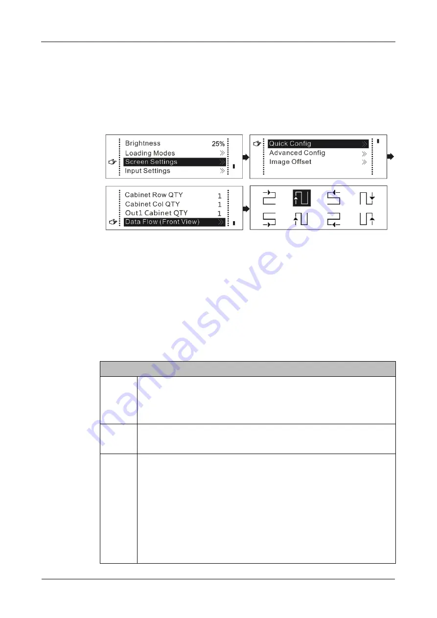
6.3.1 Quick Configuration
Step 1 Check to ensure the LED screen is powered on and displays normally.
Step 2 Press the knob to enter the operation menu screen.
Step 3 Choose
Screen Settings
>
Quick Config
to enter the submenu of
Quick Config
.
Step 4 Set
Cabinet Row QTY
and
Cabinet Col QTY
(number of cabinet rows and columns)
based on actual conditions.
Step 5 Set
Out1 Cabinet QTY
(number of cabinets loaded by the Output 1). (The device has
restrictions on loading capacity of the output. For details, see the first note item in the
table below.)
Step 6 Set
Data Flow (Front View)
by selecting one from the eight data flow presets. (For
details, see the third note item in the table below.)
Note
a
When the Output 1 (OUT1 and IN1) and Output 2 (OUT2 and IN2) are
used together at the same time, the number of cabinets loaded by the
Output 2 must be less than or equal to the number of cabinets loaded by
the Output 1.
b
If the screen loaded is irregular (sizes of the screen's cabinets are
different), NovaLCT must be connected to configure the screen.
c
During data flow setting, pay attention to the following points.
To set the data flow, rotate the knob to select
Data Flow (Front
View)
and press the knob to enter the data flow preview screen.
Then, select one from the eight data flow presets. At last, press the
knob to save the setting and press the
BACK
button to exit the
current operation.
Ensure that the cabinets are connected one by one according to
one direction
Ensure that the Ethernet Port 1 is at the beginning position of the
whole data flow.
XI'AN
NOVASTAR
TECH
CO.,
LTD.


