5
ASSEMBLE INSTRUCTIONS
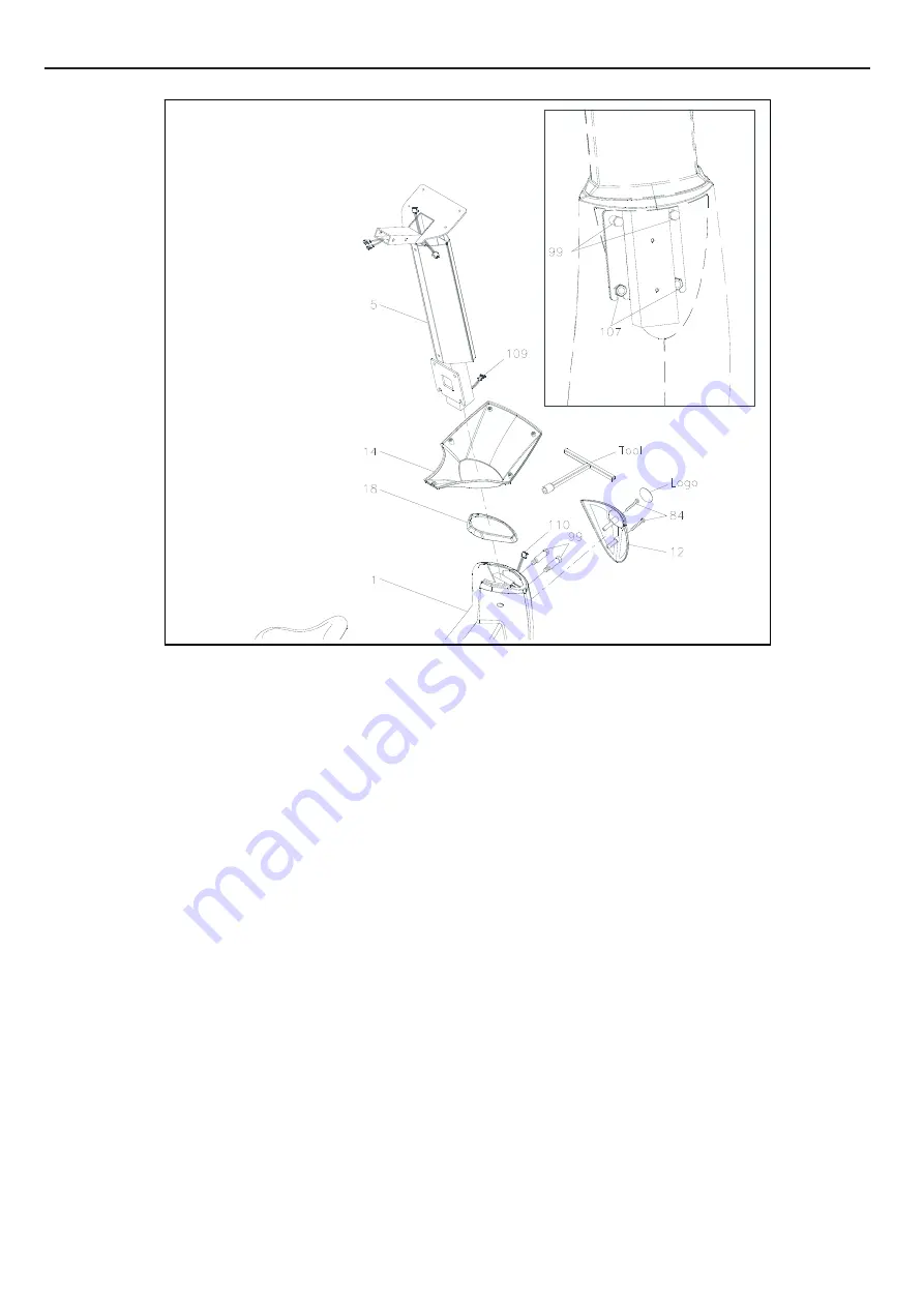
STEP 3
Slide the
Console Bracket (14)
and the
Upright Sleeve (18)
onto the
Upright Post (5.)
Make sure the direction of the
Upright Post (5)
is in the correct direction as shown.
Be careful not to damage the
Middle Connection Wire (109)
while doing assembly Step 3 to 4
STEP 4
a. Make sure 2 pcs
Nylock Nuts (M10) (107)
have already inserted into the front of the
Main Frame (1)
as the illustration shown on the top right corner
b. Insert the
Upright Post (5)
into the
Main Frame (1)
and secure with the
Bolt, Hex Head
(M10xp1.5x50mm)(99)
by using the
T-HEAD SOCKET WRENCH (17MM)
as shown.
STEP 5
a. Connect the
Middle Connection Wire (109)
to the
Lower Connection Wire (110.)
b. Attach the
Front Decorating Upright Cover (12)
onto the front of the
Main Frame (1
) with the
Screw,
Round Head (M5xp0.8x50mm)(84.)
c. Paste a Logo Sticker on the surface of the
Front Decorating Upright Cover (12.)
A logo sticker is included in the hardware box.
d. Slide the
Upright Sleeve (18)
down to cover the open area of the
Main Frame (1.)
Содержание UG-7020
Страница 34: ...33 PRODUCT PARTS DRAWING...


