North Ridge Pumps NOVA ROTORS MN Series Скачать руководство пользователя страница 30


Pag.29                                 (Funct. and Maint.Manual n.03 – Fourth edition)           OMI.EN-PCP001   R01                               


9.4.2.1.2. RE-ASSEMBLY 
 

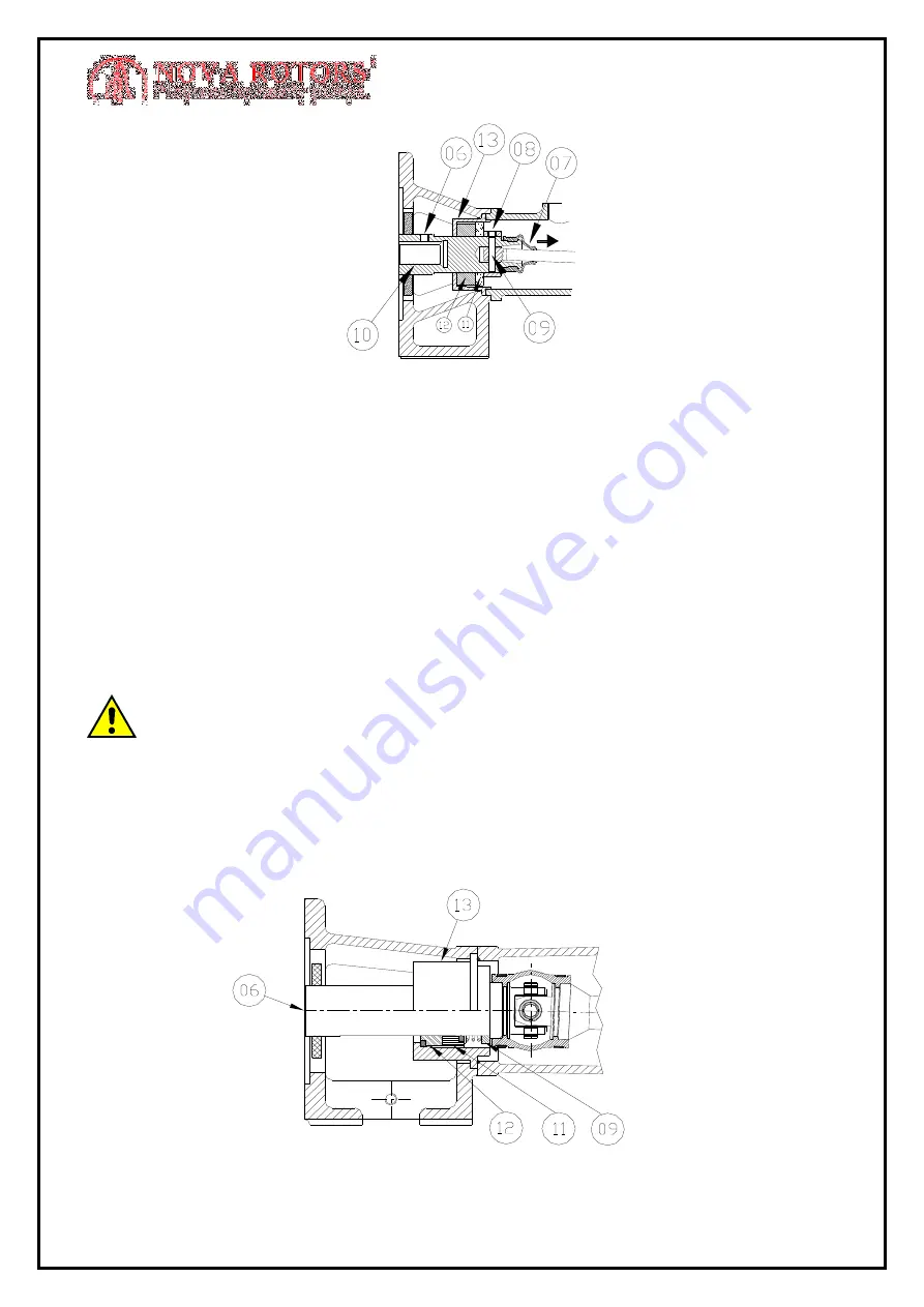
1. Check the condition of O’Rings, seal and stationary seat faces. 
2. Check the condition of the hollow shaft. 
3. Clean the hollow shaft, the housing (13) (see picture above) and all involved parts. 
4. Clean and oil the propeller shaft (Rust jams the shafts coupling, thus increasing the 

danger of damage during disassembly). 

5. Wet with glycerine the hollow shaft (10) and the bush (08) on the involved area to 

ease the insertion of the mechanic seal. 

6. Carefully clean the seal faces before assembly. 
7. Perform the steps backwards described in Chap. 9.4.2.1.1. 


 DANGER: During re-assembly, it is necessary to distribute the pressure uniformly 

on the fixed ring, to prevent malfunctioning or failures. 
 
9.4.2.2 Single mechanical seal (TEN4) for 030, 040, T062-1 pumps type  


Содержание NOVA ROTORS MN Series

Страница 1: ...eet X Cel House Chrysalis Way Langley Bridge Eastwood Nottinghamshire NG16 3RY Tel 44 0 1773 302 660 Email sales northridgepumps com Website www northridgepumps com FUNCTIONING AND MAINTENANCE MANUAL...

Страница 2: ...es of every pump Some pictures in this manual may show parts that might be slightly different from the ones assembled on the pump The manual is an integral part of each pump therefore it must be kept...

Страница 3: ...physical properties differ from the ones set out in the order The max pressure required must be lower than the max pressure a pump can reach adequately reduced to take into account any leakage from de...

Страница 4: ...s installed close to the pump must be protected with casings ranked IP 66 or higher 1 6 3 Mobile parts of pump The rotor of the progressing cavity pump is connected to the driving unit through a joint...

Страница 5: ...e Such non compliance may result in inability to perform any key functions of the pump and or plant damage to the pump and or plant electric mechanical and chemical dangers for people danger for the e...

Страница 6: ...nning inside the stator In progressing cavity pumps the axis of rotation of the rotor A does not coincide with the axis of rotation of the motor The rotor is driven by a double joint shaft This shaft...

Страница 7: ...vity pumps are divided into two main categories according to the coupling between pump and motor Progressing cavity pumps WITH BEARING HOUSING Progressing cavity pumps CLOSED COUPLED 3 3 Motors Motors...

Страница 8: ...0014 Note It is possible to manufacture teflon stators for special applications 4 3 Couplings 4 3 1 Bearing housing coupling Using the bearing housing coupling the pump is linked to the motor by the m...

Страница 9: ...Pin joint for use with foods without sleeve Type SN8 Pin joint with short bell and flat sleeve Type SN9 Pin joint with short bell for high power Type SN10 Pin joint with short bell type C 4 5 Sealing...

Страница 10: ...lve set to the desired pressure and a bypass pipe which closes delivery or reduces the flow in case the pump may not be stopped 4 6 3 Return valve in delivery In case it is necessary to convey part of...

Страница 11: ...ft the pump using the motor or reduction gear eyebolts They are meant for transport of motor or reduction gear only Due to the diversification of configurations these are to be considered as general i...

Страница 12: ...phase The connecting to the Neutral must be coherent with safety system of installation plant TT TN etc Before starting the pump check tension frequency and number of phases conform with the electric...

Страница 13: ...ation order The direction of pump rotation sets the direction of the flow through the progressing cavity pump Any different setup must be agreed with the supplier and approved by the same By changing...

Страница 14: ...to provide lubrication at startup Minimize the air intake in the body pump Note In case fluxed packing glands or fluxed mechanical seals or quenches were used the feeding system connections and system...

Страница 15: ...life and high performance it is useful to follow these recommendations The pump is self priming but it is advisable to fill its body with the liquid to be pumped before the first startup Control the...

Страница 16: ...nt In this cycle the stator is subject to high chemical and thermal stress Therefore in this CIP cycle the pump shall stop and restart that is change the relative position of rotor and stator every 2...

Страница 17: ...cleaned Through the cleaning windows if present on the pump body Manually disassembling the pump Automatically CIP for pumps with suitable connectors 8 2 Stators and sealing systems 8 2 1 Stators App...

Страница 18: ...e most stressed parts of the pump therefore needs regular and adequate controls On any kind of joint it is always necessary though the pump may work normally to immediately replace damaged sleeves eve...

Страница 19: ...F G H I J POSSIBLE CAUSE 1 X X New stator and rotor are stuck together 2 X X Faulty electrical contact 3 X X X X X Excessive delivery pressure 4 X X X X Unknown matter in the pump 5 X X X X X High te...

Страница 20: ...hanical seal is used carefully clean and replace it if necessary 12 Increase rpm 13 Modify electric connections 14 Increase the pressure at the inlet lowering the pump position and lower the inlet flu...

Страница 21: ...black arrow see below until they were completely free 9 1 1 Ceramic rotor Ceramic rotors require particular care and no force of any kind In particular hammer strikes concussions and collisions are to...

Страница 22: ...ng torque is about 40 50 Nm Do not over tighten screws and tie rods See table below Screw Dia M6 M8 M10 M12 M16 M20 M24 M30 Torque Nm 8 15 30 45 75 80 100 12 DANGER When inserting the rotor into the s...

Страница 23: ...be free SN1 9 3 3 Joint type SN2 1 Remove the clamps 3 2 Remove the sleeve 4 by levering with a screwdriver 3 Remove the 2 retaining rings 5 that holds the pin Then after removing the pin and the spid...

Страница 24: ...s and pin 13 will be visible 6 Beat the pin with care taking care not to damage the bell 14 Then if necessary the pin and the bushes can be replaced 7 Pull the sphere in the direction of the black arr...

Страница 25: ...nt during the maintenance cycles SN5 This kind of joint has no spare parts available In case of malfunctioning it shall be fully replaced 9 3 7 Joint type SN6 1 Remove the screws 21 on the rotor side...

Страница 26: ...The bushing and the pin 31 will then be visible 4 Beat the pin with care taking care not to damage the bell 32 Then if necessary the pin and the bushes can be replaced 5 Pull the sphere in the direct...

Страница 27: ...the sphere in the direction of the black arrow Since it is integral with the propeller shaft 41 they ll both be free of the joint Then the hexagonal head screws holding the bell to the rotor or hollo...

Страница 28: ...the transmission draw back the sphere and remove the hexagonal head screw located inside the bell Follow the previous operations on the contrary way to reassembling 9 4 Replacement of seals 9 4 1 Pac...

Страница 29: ...the pump motor by extracting it in the direction of the black arrow 3 Move the sleeve 07 in the direction of the black arrow 4 Unscrew the grub screw from the bush 08 in order to be able to move it a...

Страница 30: ...ust jams the shafts coupling thus increasing the danger of damage during disassembly 5 Wet with glycerine the hollow shaft 10 and the bush 08 on the involved area to ease the insertion of the mechanic...

Страница 31: ...with the body pump pay attention to the OR ring conditions between them Substitute it if damaged see the pump s section draw recommendable to DANGER to make the mechanical seal assembling easier it i...

Страница 32: ...in the hollow shaft make sure the grub screw slot 11 coincides with the threaded hole 02 in the hollow shaft then the mechanic seal will be correctly positioned Otherwise push the propeller shaft as...

Страница 33: ...inside see picture B 6 Remove the separating ring 05 the mobile part of the seal 06 and the fixed part 07 WARNING In bearings mounted pumps as in the picture above before inserting the hollow shaft 0...

Страница 34: ...drive shaft 3 Take out the packing gland 4 Remove the circlip 71 blocking the bearings 5 Unthread the bearings 6 Remove the second inner circlip 71 7 Exctract the mechanical seal 23 handling with car...

Страница 35: ...it the male shaft using a plastic hammer following the body pump direction till the bearing 74 come out from the male shaft be careful to keep straight and not superimposed 4 Remove the hexagonal head...

Страница 36: ...he housing 53 and extract the mechanical seal 23 handling it with care extract the oil seal 35 9 4 5 2 Re assembly 1 Check the seal OR rings and faces 23 integrity 2 Check the female drive shaft condi...

Страница 37: ...raph the optional is a threaded hole quench used for internal washing itself 9 4 7 Single mechanical seal TEN10 for pump mod 010 9 4 7 1 Disassembling 1 Remove the screws from the outlet flange 2 Unsc...

Страница 38: ...aded inside the transmission must be placed on the backing of the female drive shaft without needing a pre load 10 MECHANICAL SEALS WITH BLOCKING SEAL FOR BARE SHAFT PUMP This mechanical seal blocking...

Страница 39: ...tor warming is not significant 11 1 2 Working conditions In compliance with IEC 34 1 the motors can work under the following working conditions 1 Ambient temp C between 16 and 40 2 Elevation less than...

Страница 40: ...with the instructions included in this manual 4 1 7 Start up operation and maintenance 4 1 8 Safety warning for maintenance inspection and assembly 4 1 9 Alteration and discretionary production of spa...

Страница 41: ...16 8 2 2 Seals 16 8 3 Control and replacement of articulated joints 17 8 4 Lubrication 17 8 4 1 General 17 8 4 2 Bearings 18 8 4 3 Propeller shaft joints 18 8 4 4 Motor variator 18 8 5 Malfunctioning...

Страница 42: ...seal with QUENCH TEN9 36 9 4 7 Single mechanical seal TEN10 for pump mod 010 36 10 MECHANICAL SEALS WITH BLOCKING SEAL FOR BARE SHAFT PUMP 37 11 MOTORS 38 11 1 Useful informations 38 11 1 1 Type of s...

Отзывы: