Fans
Fan wheels and housings should be checked for dirt
buildup. If the forward curved supply or exhaust fan is
dirty, it will be necessary to remove the blower assembly
to clean the dust out through the fan discharge.
The forward curved supply or exhaust fan is fitted with
regreasable bearings. The grease type, quantity and
regreasing interval depends on bearing (fan size) and rev-
olutions per minute (rpm) and are indicated in the tables in
. Clean the grease nipple first, then rotate the
fan shaft slowly by hand while regreasing. The regreasing
intervals are theoretical and will depend on site conditions,
hours of operation and temperature. It is recommended
to make periodic inspections of the bearings before these
theoretical intervals.
Forward Curved Supply or Exhaust Fan and
Motor
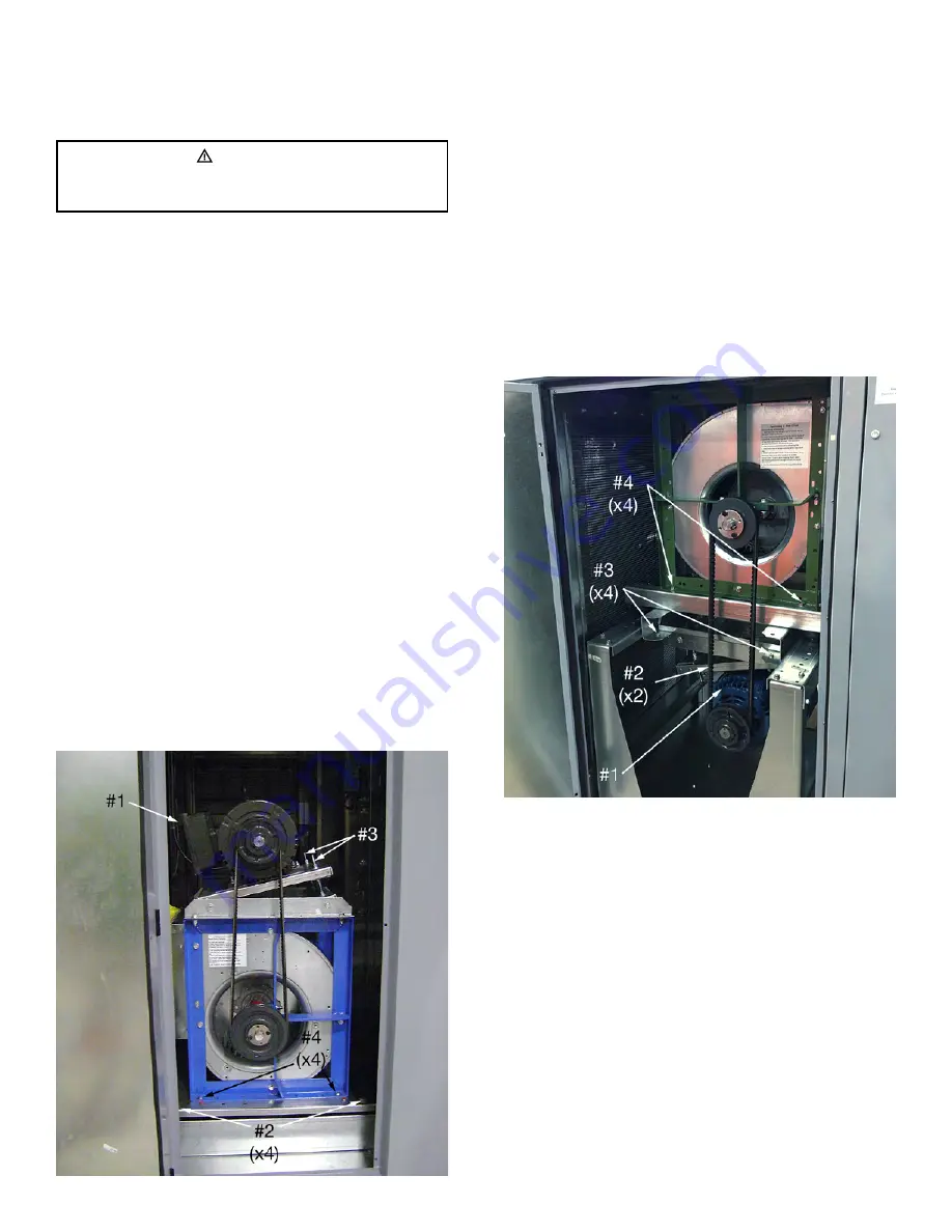
To remove the motor and blower on units with down, side
or end discharge, disconnect the four-wire service con-
nector from the motor (#1, Figure 4). Loosen the four bolts
(#2, Figure 4) and all screws that fasten the blower to the
flex collar. Slide the fan assembly out of the unit. The fan
assembly may have to be lifted over the fan assembly
plate bolts (#3, Figure 4).
To remove the motor and blower on units with a gas-fired
furnace option or with top supply or exhaust discharge,
disconnect the four-wire service connector from the motor
(#1, Figure 5). Loosen the two adjustment bolts (#2, Figure
5) on the base plate. Rotate the motor and base plate to
remove the belt. Remove the four bolts (#3, Figure 5) and
slide the motor assembly out. To remove the blower, re-
move the four bolts (#4, Figure 5) and all screws that fasten
the blower to the flex collar. Slide the blower out.
The belt tension is adjusted by the positioning of the rotat-
ing motor base plate. Loosen the two adjustment bolts
(#4, Figure 4 or #2, Figure 5) on the base plate. Rotate the
motor and base plate to achieve the maximum belt deflec-
tion as described under belt tension adjustment below.
Tighten the adjustment bolts (#4, Figure 4 or #2, Figure
5). Verify that the sheave and pulley faces are still parallel.
The fan rpm can be adjusted to achieve the design airflow
by setting the adjustable sheave on the motor shaft. The
pulley set screw torque setting is 110 in-lbs to 130 in-lbs.
Belt Tension Adjustment
1. Measure the belt span with a span scale (see Figure
2. Divide the belt span by 64 to determine the belt de-
flection needed to check tension.
3. Set the O-ring on the span scale to the required de-
flection value.
4. Set the small O-ring at zero on the force scale.
WARNING
Disconnect the main power switch to the unit before per-
forming service and maintenance procedures.
Figure 4: Motor and blower orientation for down, side
and end supply/exhaust options
Figure 5: Motor and blower orientation for gas units
and top supply/exhaust options
VCES-VHC-IOM-1F – VHC-36, -42 & -50
20


