background image

1

Preparing for the Network

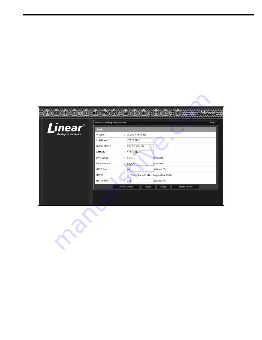
To allow for the EN Series unit to be recognized on the local network, it is necessary to change the controller’s IP address.

1.  Connect your programming computer directly to the Ethernet port of the controller.
2.  Assign a static IP address of 192.168.0.149 to the computer. (For instructions on how to change the static IP address of a Windows computer, 

please visit: http://technet.microsoft.com/en-us/library/ff 710457).

3.  After assigning the static IP address, open a web browser and enter the IP address of the controller (Default = 192.168.0.250).
4.  The controller presents the Linear login page. To log on, enter the default user ID and password (admin/admin).
5.  Browse to the Network Configuration (IP address) page as shown. Enter the static IP address, Subnet Mask, Gateway and DNS server 

(provided by the network administrator) so that it matches the requirements of the local network.

6.  Click Save & Reboot and the system will reboot. (Reboot will take approximately 2 minutes.) 

NOTE: The system data will be lost if the controller is powered down without performing Save & Reboot.

7.  Disconnect the programming computer from the control panel. The system is now ready for the local network

Connecting the Network

1.  Pull an Ethernet cable through the opening in the enclosure nearest the Ethernet port.
2.  Plug the RJ-45 connector into the Ethernet port on the controller.
3.  Connect to the local area network (LAN)
4.  If the network connection is functioning properly, the LAN LEDs on the control panel will illuminate. The local computers will then be able to 

access the system by entering the IP address of the controller.

.

Содержание EN-2A10

Страница 1: ...EN Series EXN Telephone Entry Access Control System Quick Start Guide P N EN 2A4 EN 2M4 EN 2A7 EN 2M7 EN 2A10 EN 2M10 and EXN EN 2A4 EXN...

Страница 2: ...g various computers and peripherals to the Internet the unit s LAN PORT is sufficient for connecting the system The unit will need to be configured with the correct network settings before connecting...

Страница 3: ...tion IP address page as shown Enter the static IP address Subnet Mask Gateway and DNS server provided by the network administrator so that it matches the requirements of the local network 6 Click Save...

Страница 4: ...n Click Scan to search the network for controllers 5 When controllers are identified they will be listed in IP Installer Configuring the Server and Client The default IP address of the server and clie...

Страница 5: ...the same software revision Refer to Nortek Security and Control technical support for assistance in determining and or updating the software revision 1 Locate the panels MAC address Option 1 Locate on...

Страница 6: ...screen 8 Enter information into the correct fields 9 Click next 10 Apply power to TE Display unit 11 Log into the controller and verify what version system software is running 12 Log into your system...

Страница 7: ...d Edit key to change the license key 15 Click on the Edit key and past the new license 16 Click Save NOTE The TE Front End is now a client which can be added to the EN Models as an expansion Module Th...

Страница 8: ...data into data entry boxes A denotes required information 4 The Card Number data entry line information can be input manually or the card can be scanned 5 In the Access Level section assign the Type...

Страница 9: ...ransmitter is decoded and if the conditions for granting access are fulfilled the programmed relay channel will activate for the programmed time If the Anti passback feature is enabled the transmitter...

Страница 10: ...Number RA Contact Nortek Security Control Returns at 1 855 546 3351 for an RA and other important details FCC Notice Changes or modifications not expressly described in this manual or approved by the...

Отзывы: