10-10
Page 11
2008-10-01
B. Safety Water Level Control Check
(1)
To ensure safe operation, the humidifier constantly monitors the back up float of
the humidifier and also performs float checks at regular intervals.
C. Self Diagnostic
(1)
This feature allows the user to activate various hardware elements within the
system to prove operational compliance.
D. Energy Efficient Blowdown Sequence – Unique to Nortec
(1)
Fill valve and blow down sequences are based on steam production and not time
of operation to increase efficiency of the unit. If the demand signal controls the unit
at the minimum output, of 25 lbs/hr, only 25% of 25 lbs/hr will be drained.
E. Internal Drain Water Tempering
(1)
The unique design for the internal Drain Water Cooler from NORTEC will ensure
water tempering at all times of the water going to drain. The fresh fill water will
completely mix with incoming hot water from the tank during blow down or drain
cycles and ensure water does not exit the system at more then 140ºF (60ºC).
(2)
When the “SMART” feature is enabled on the TC version, the temperature of the
tank is monitored and fresh cold water will be used only when drain water is above
140ºF (60ºC).
F. Capacity Turn Down
(1)
The GS humidifier is capable of full modulation of the output of each burner down
to 25 lbs/hr. For example on a four-burner system, such as the GS 400, the
turndown ratio is 6% of total output.
(2)
When the control signal requires less than 25 lbs/hr output, the internal controller of
the unit takes over with a unique time proportioning algorithm and to control the
output and modulate down to 0 lbs/hr.
G. GSTC Unit Networking
(1)
The new TC controller of the GS Series allows staged modulation through
networking of up to 10 units when higher capacities of steam require multiple units.
The modulating signal will be wired to the master unit and this one will control the
output of the other units for seamless modulation from 25 lbs/hr up to 6300 lbs/hr.
All units will be configured as master or staged. The operational range of each unit
will be set in the internal controller at the factory. A control modulation signal to the
master unit and a three-wire connection between each unit being staged is all that
is required.
2. CONTROLS
A.
Introduction
(1) The GSTC model features a backlit alphanumeric keypad for user interface, which
allows for adjustment of operating parameters and displays system operating status.
(2) The GSP model uses status indication lights.
Содержание GS Series GSP Indoor
Страница 1: ...1503540 C GS Series GSTC GSP Indoor GSTC Outdoor Engineering Manual ...
Страница 7: ...2008 10 01 THIS PAGE INTENTIONALLY LEFT BLANK ...
Страница 8: ...10 00 Page 1 2008 10 01 10 00 PRINCIPLE OF OPERATION ...
Страница 10: ...10 00 Page 3 2008 10 01 Figure 1 GS Indoor Series Figure 2 GS Outdoor Series ...
Страница 11: ...10 00 Page 4 2008 10 01 Figure 3 GSTC Key Pad Figure 4 GSP Key Pad ...
Страница 13: ...10 00 Page 6 2008 10 01 THIS PAGE INTENTIONALLY LEFT BLANK ...
Страница 14: ...10 10 Page 7 2008 10 01 10 10 OPERATION ...
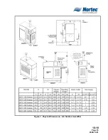
Страница 17: ...10 10 Page 10 2008 10 01 Figure 3 Physical Dimensions GS Outdoor Humidifier ...
Страница 21: ...10 10 Page 14 2008 10 01 Figure 4 GSTC GSP Indoor Clearance Figure 5 GSTC Outdoor Clearance ...
Страница 23: ...10 10 Page 16 2008 10 01 THIS PAGE INTENTIONALLY LEFT BLANK ...
Страница 24: ...10 20 Page 17 2008 10 01 10 20 MAINTENANCE ...
Страница 27: ...10 20 Page 20 2008 10 01 THIS PAGE INTENTIONALLY LEFT BLANK ...
Страница 28: ...10 30 Page 21 2008 10 01 10 30 OPTIONS ACCESSORIES ...
Страница 34: ...10 30 Page 27 2008 10 01 Figure 3 Steam Distributor Figure 4 Blower Pack Figure 5 Short Absorption Manifold ...
Страница 35: ...10 30 Page 28 2008 10 01 THIS PAGE INTENTIONALLY LEFT BLANK ...
Страница 36: ...10 40 Page 29 2008 10 01 10 40 SPECIFICATION ...
Страница 44: ...10 40 Page 37 2008 10 01 THIS PAGE INTENTIONALLY LEFT BLANK ...


