Norselight HR 250 R20 Page 6 of 18
__________________________________________________________________________________________
NT 2560E – A(04.05)
3. Installation
3.1. Mechanical installation
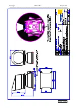
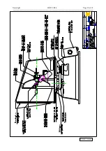
The searchlight must be mounted on a straight plate using 4 stainless screws.
See drawing D-R20-06.
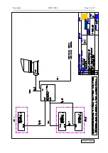
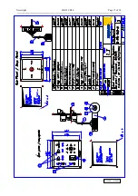
The main control panel is constructed for installation indoors on the bridge. See
drawing D-R10-R40-01.
The sub control panel where applicable is constructed for console or bulkhead
mounting and it is supplementary equipment, see drawing D-R10-R40-01. Both
mainpanel and subpanel can be delivered in protected cabinet as addition.
3.2. Electric installation.
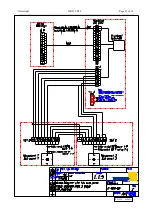
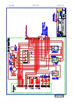
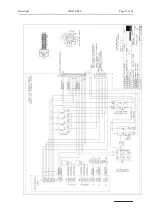
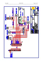
Power supply to the control unit 24V DC (drawing E-R20-51), 115/230V AC
(drawing E-R20-50)
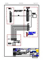
Power supply to the lamp unit-24V DC according to drawing: E-R20-24
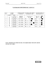
Before one or more subpanels are connected, remove the two straps on the
connection block TB1A. Look at drawing E-R20-06, E-R20-07, E-R20-24,
E-R20-50 and E-R20-51 to identify the correct block.


