background image

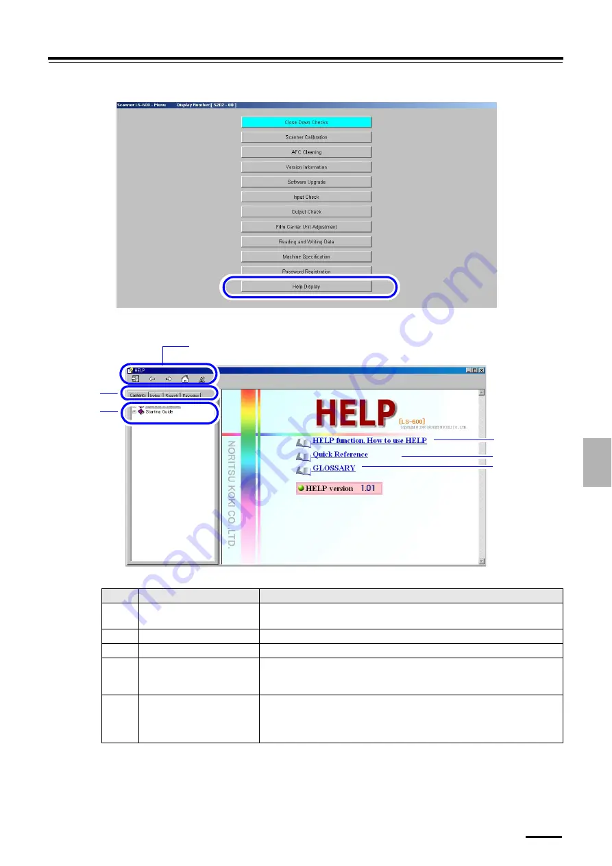
7.1 Accessing the HELP display

7 – 3

7.

How to

 ac

ce

ss

 the

 HELP d

is

p

la

y

Example: 

Menu

 display

The 

Help

 display is shown.

Example: 

HELP

 display

The numbers in the table below correspond to those in the illustration above.

No.

Item

Explanation

1

HELP  functions,  How  to  use
HELP

Explains how to use HELP, such as the explanation of the buttons in the 

HELP

display and how to search.

2

Quick Reference

Allows you to see common inquiries.

3

Glossary

Explains terms and digital terms necessary for operating the product.

4

Buttons on the 

HELP

 display

Allows you to view the HELP display. Allows you to return to the previous page
or  change  character  size  on  the  display.  For  details  about  how  to  use  these
buttons, see 

HELP Functions and how to use HELP

 (No. 

1

) .

5

Contents
Index
Search
Favorites

Allows you to use any of these functions, 

Search from Contents

Search from

Index

Search from all texts with a keyword

 and 

Add to Favorite

. For details

about how to use these buttons, see 

HELP Functions and how to use HELP

(No. 

1

) .

S5202-00-UM03

4

6

5

1

2

3

S088497

Содержание LS-600

Страница 1: ...ormation you need to know before operating this product 1 For your safety 2 Getting Started 3 Turing power on off 4 Emergency operation 5 Mastering basic operations 6 Daily maintenance 7 How to access...

Страница 2: ...This page is intentionally blank...

Страница 3: ...eavily damage the manual contact your place of purchase Issued in April 2007 It is prohibited to dopy or reproduce this manual This manual is subject to change without notice Illustrations in the manu...

Страница 4: ...the trademarks of their respective owners Trademark symbols and are not shown in the manual itself Export Control This Product shall be exported pursuant to the Japan Foreign Exchange and Foreign Tra...

Страница 5: ...opics you need to know before using this product Turing power on off This section explains how to turn the product s power on and off Emergency operation This section explains the procedure to turn of...

Страница 6: ...d density on the Judgment Display Operations performed when necessary This section explains saving and loading the scanner setting data or upgrading the program etc Troubleshooting This section explai...

Страница 7: ...procedures that require caution and instructions that must be followed This is called the alert symbol Text following this symbol contains particularly important information concerning safety Be sure...

Страница 8: ...rocessable film size 2 5 2 3 3 Processable film length 2 5 2 3 4 Problematic films and corrective actions 2 6 2 3 5 Processing an IX240 film cartridge that cannot be scanned 2 9 3 Turing power on off...

Страница 9: ...lass 6 7 6 3 2 Cleaning the 135 rewinding unit 6 8 6 3 3 Cleaning each roller and the film path of the film feed unit 6 11 6 3 4 Cleaning each brush of the film feed unit 6 13 6 3 5 Cleaning the magne...

Страница 10: ...This page is intentionally blank...

Страница 11: ...1 1 1 1 For your safety This section explains general safety precautions Read these precautions thoroughly and carefully...

Страница 12: ...the warning labels The warnings include a signal word the type and extent of the danger and information on avoiding the danger Carefully read and understand the warnings included in this manual and on...

Страница 13: ...ypes of warning labels on this product Follow the instructions on the labels carefully in order to operate the product safely and avoid accidents Do not remove labels If a label becomes illegible or c...

Страница 14: ...er supply then contact your place of purchase Precautions against electric shock Do not remove covers while the power code of this product is connected Doing so presents a risk of electrical shock An...

Страница 15: ...1 3 For your safety 1 5 1 For your safety 1 2...

Страница 16: ...uct Problems caused by connecting devices other than those specified by us are not covered by our warranty Do not damage break bind up or cut the power cord Placing a heavy load on the power cord pull...

Страница 17: ...ched by the dust Be sure to remove dust Handling an IX240 film cartridge Keep film cartridge away from items with magnetic fields in which the magnetic data for printing is stored Do not allow the mag...

Страница 18: ...This page is intentionally blank...

Страница 19: ...2 2 1 2 Getting Started This chapter explains contents or precautions you should know before using this product...

Страница 20: ...HELP manuals of the EZ Controller and the printer see each Starting Guide 1 Supplied in a hard copy CD and HELP 2 Supplied in CD and HELP Hard copy manual s CD HELP Starting Guide 1 Operator s Manual...

Страница 21: ...whether or not the product is ready to process film Lights in green Shows that you can insert film into the product Blinks in green Shows that the product is starting up It also shows that the produc...

Страница 22: ...ket Flip the transfer switch down Turning on the power supply of the PC starts up this product If supplying power from the connected printer Flip the transfer switch up Activating the printer starts u...

Страница 23: ...responds to one frame of a 135F film A curled film irregular film ends or broken perforations holes on the both sides may cause film jams in the film feed unit Check the film condition and take correc...

Страница 24: ...into pieces One that is cut into pieces is not processable NOTE The following length is required for IX240 type film cut by the optional front edge reshaper or rear edge reshaper Symptom Corrective ac...

Страница 25: ...d hold the film with your hands so that it dose not twist while it is being inserted into the film carrier Symptom Corrective action The film does not have a straight end If the leading or rear end is...

Страница 26: ...e splicing tape The check label is attached to the film If you process a film with the check label on it cut off the unnecessary part Cut the film 2 mm or more away from the label attaching position D...

Страница 27: ...idge normally Replace the IX240 film into the spare cartridge if it is either of the following The cartridge is damaged The label comes off or it is coming off from the cartridge Perforations are cove...

Страница 28: ...This page is intentionally blank...

Страница 29: ...3 3 1 3 Turing power on off This section explains how to turn the product s power on and off...

Страница 30: ...e scanner 1 Check whether the USB cable is correctly connected 2 Turn on the power supply of the PC This product starts up 3 1 2 Closing down the product There are two methods to close down this produ...

Страница 31: ...operation This chapter explains how to restart this product when an error occurs how to turn off the power supply in an emergency and how to take corrective actions for the case that the scanner make...

Страница 32: ...o reserve the error or attention Reserving the error allows you to perform operations temporarily 2 Exit all applications 3 Turn off the power supply of the PC 4 Turn on the power supply of the PC 5 A...

Страница 33: ...over Scanning stops Confirm that no film is jammed Remove jammed film if any For instructions on how to remove jammed film see 6 8 1 Corrective actions for 135 film jam or 6 8 2 Corrective actions for...

Страница 34: ...This page is intentionally blank...

Страница 35: ...5 5 1 5 Mastering basic operations This section explains procedures about how to access the Scan Setting display or scanning operation...

Страница 36: ...ware such as Adobe Photoshop No Name Functions Environment display This is a display where scanning methods settings are configured such as the image correction frame feed and frame number For details...

Страница 37: ...5 1 Scan Setting display 5 3 5 Mastering basic operations 2 Select File Read LS 600 Example Display of Adobe Photoshop The Scan Setting display is shown S087590...

Страница 38: ...1 Accessing the Environment display If the display is accessed from the EZ Controller For details see the EZ Controller Starting Guide Accessing the scanner and printer screens If accessing the displ...

Страница 39: ...tings Environment Correction tab in the Operator s Manual 1 Film Carrier tab Frame feed and frame number settings can be configured on this display For details see 3 2 Configuring settings of frame ad...

Страница 40: ...oller Starting Guide Accessing the scanner and printer screens If accessing the display from a stand alone scanner There are two methods to access the Menu display from a stand alone scanner Step 1 Cl...

Страница 41: ...Scanner Calibration in the Operator s Manual 1 AFC Cleaning Allows you to clean the film feed section For details see 7 2 1 Cleaning the film feed section AFC Cleaning in the Operator s Manual 1 Versi...

Страница 42: ...white margin for positive is printed on the front end or rear end Scan Position Auto Correction in the Operator s Manual 1 Reading and Writing Data Allows you to save and load the scanner setting dat...

Страница 43: ...For details about the precautions in handling films see 1 5 Precautions for handling films 1 Confirm the power supply of the flatbed scanner is on 2 Access the Scan Setting display Accessing the Scan...

Страница 44: ...scanner Confirm the scan condition and click Scan button Temperature adjustment of scanner complete ready for configuring settings Insert film Ready for scanning Scanning Scanning Film Carrier Select...

Страница 45: ...matic High Quality the quality is given priority in scanning This takes more time for processing than Automatic High Speed NOTE The print quality and processing capacity depend on which print sizes ar...

Страница 46: ...from the largest frame number The 135 film is fed into the film feed unit and the scanning process starts After scanning finishes the Judgement Display is shown The Judgement Display is shown only whe...

Страница 47: ...ght click on an image to skip it Then it will not be scanned Example Judgment Display 9 Confirm the image area of the scanned image For images whose position is not easy to adjust such as a night scen...

Страница 48: ...ed for the correction values of 10 or more or 10 or less 11 Click the DSA button and adjust Contrast Sharpness and Chroma Example Judgment Display The DSA display is shown Correct the image if necessa...

Страница 49: ...7 1 Accessing the HELP display Example DSA display NOTE The DSA display can also be accessed from the Functions display Example Functions display 12 Move the frame to the next image by pressing the ke...

Страница 50: ...Example Judgment Display Scanned image is displayed onscreen 15 Click Close on the Scan Setting display Example Scan Setting display 16 Save the image that is displayed onscreen to any destination us...

Страница 51: ...TE It is also possible to process the IX240 film taken out of the cartridge For details about how to process the film taken out from the cartridge refer to 5 6 Scanning IX240 film taken out of the car...

Страница 52: ...the scanner Confirm the scan condition and click Scan button Temperature adjustment of scanner complete ready for configuring settings Insert film Ready for scanning Scanning Scanning Film Carrier Sel...

Страница 53: ...is given priority in scanning This takes more time for processing than Automatic High Speed NOTE The print quality and processing capacity depend on which print sizes are used For example when the pri...

Страница 54: ...Press the eject button in the direction shown by the arrow to raise the cartridge holder 2 Adapt the IX240 film cartridge to the holder and lay the holder The IX240 film is fed into the film feed unit...

Страница 55: ...ation if AUTO is selected in PJP AUTO Switch on the Correction tab of the Environment display Next operate with image editing software 7 Click the image to correct color and density Right click on an...

Страница 56: ...d density correction button 2 Perform correction Example Judgment Display Alphabetical letters from A to F are substituted for the correction values of 10 or more or 10 or less Key Explanation F10 key...

Страница 57: ...or details see 4 1 4 Corrections of contrast and sharpness DSA in the Operator s Manual For details about how to use the Operator s Manual see 7 1 Accessing the HELP display Example DSA display NOTE T...

Страница 58: ...you do not have any more images to output go to the next step Example Judgment Display Scanned image is displayed onscreen 14 Click Close on the Scan Setting display Example Scan Setting display 15 S...

Страница 59: ...Operator s Manual of the EZ Controller For details about the precautions in handling films see 1 5 Precautions for handling films 1 Confirm the power supply of the flatbed scanner is on 2 Access the...

Страница 60: ...tment of the scanner Confirm the scan condition and click Scan button Temperature adjustment of scanner complete ready for configuring settings Insert film Ready for scanning Scanning Scanning Film Ca...

Страница 61: ...quality is given priority in scanning This takes more time for processing than Automatic High Speed NOTE The print quality and processing capacity depend on which print sizes are used For example whe...

Страница 62: ...n out of the cartridge 5 28 4 Click Scan 5 Put on clean gloves 6 Press the eject button to raise the cartridge holder 7 Attach the IX240 film adapter S5200 00 UM01 Eject button Cartridge holder G07184...

Страница 63: ...n the Correction tab of the Environment display For details about the Judgement Display see 4 1 Configuring color and density settings in the Operator s Manual For details about how to use the Operato...

Страница 64: ...n adjustment function For details see 7 4 If a film that has unclear frame boundaries is processed in the Operator s Manual For details about how to use the Operator s Manual see 7 1 Accessing the HEL...

Страница 65: ...and Chroma Example Judgment Display The DSA display is shown Correct the image if necessary For details see 4 1 4 Corrections of contrast and sharpness DSA in the Operator s Manual For details about...

Страница 66: ...the keys or then perform Step 11 to Step 13 15 Click START Example Judgment Display 16 Corrects color and density of other images If there are more images the next page is displayed 1 After you config...

Страница 67: ...e on the Scan Setting display Example Scan Setting display 18 Save the image that is displayed onscreen to any destination using image editing software such as Adobe Photoshop After saving the image c...

Страница 68: ...This page is intentionally blank...

Страница 69: ...6 6 1 6 Daily maintenance This chapter explains the necessary maintenance for maintaining the quality of this product...

Страница 70: ...ntenance items and timing Timing Part Operation Reference Weekly Checks Film feed unit cleaning the film feed section Roller Magnetic head Cleaning 6 2 1 Monthly Checks Scanner section Scanner dust pr...

Страница 71: ...the rollers or magnetic head in the film feed unit can be removed with the cleaning leader Dust accumulating on the rollers or magnetic head in the film feed unit may cause film jams Conditions Perfo...

Страница 72: ...5 Put on clean gloves 6 Insert the 240 lane cleaning leader IMPORTANT Be sure to clean both the 135 and the 240 lanes 1 Press the eject button The cartridge holder will rise 2 Attach the IX240 film ad...

Страница 73: ...Put the cleaning leader and the IX240 film adaptor back 7 When Would you like to clean the 135 lane is shown click Execute Set the Cleaning Leader is shown 8 Insert the 135 lane cleaning leader 1 Ins...

Страница 74: ...t the cleaning leader back To store the cleaning leader put the cleaning leader in a nylon bag then put it in the cleaning leader case This completes cleaning the film feed section Cleaning leader cas...

Страница 75: ...ted it is necessary to select the 240 lane by following the procedure below If the 135 lane is selected the film advance top cover cannot be opened fully 1 Slightly open the front cover then close it...

Страница 76: ...form this maintenance operation with the power on Requirements Firmly squeezed damp cloth Isopropyl alcohol Cotton swab 1 Select the 240 lane of the film feed unit IMPORTANT If the 135 lane of the fil...

Страница 77: ...nit with firmly squeezed damp cloth If it is hard to remove dirt wipe it with a cotton swab dipped in isopropyl alcohol After wiping each part dry it completely IMPORTANT Isopropyl alcohol is flammabl...

Страница 78: ...aned parts are completely dry 5 Reattach the 135 rewinding unit one knob screw Attach the 135 rewinding unit so that the square hole of the 135 rewinding unit fits the protruding section of the rewind...

Страница 79: ...e film path do not use thinner alcohol or other solvents After wiping each part using firmly squeezed damp cloth completely dry the parts Do not insert film unless the cleaned parts are completely dry...

Страница 80: ...firmly squeezed damp cloth IMPORTANT Do not touch the film path or sensors with your bare hands After wiping each part dry it completely The 135 lane The 240 lane Lock Pressing it releases the lock G...

Страница 81: ...form this maintenance operation with the power on Requirements Clean gloves Blower brush 1 Select the 240 lane of the film feed unit IMPORTANT If the 135 lane of the film advance unit is selected it i...

Страница 82: ...nd front cover If cleaning the magnetic head it is not necessary to close the film advance top cover side cover left and front cover This completes cleaning each brush of the film feed unit 6 3 5 Clea...

Страница 83: ...procedure below If the 135 lane is selected the film advance top cover cannot be opened fully 1 Slightly open the front cover then close it NOTE Closing the front cover selects the 240 lane of the fil...

Страница 84: ...ilm advance top cover side cover left and front cover This completes cleaning the magnetic head 6 3 6 Cleaning the film inserting slot of the 240 rewinding box Conditions Perform this maintenance oper...

Страница 85: ...inding box using a blower brush 6 Close the film advance top cover side cover left and front cover This completes cleaning the film inserting slot of the 240 rewinding box 6 3 7 Cleaning the air filte...

Страница 86: ...aner Procedure 1 Remove the air filter and clean it Vacuum dust from the dust accumulated surface using a vacuum cleaner If dust cannot be removed face the dust accumulated surface down and wash it un...

Страница 87: ...7 7 1 7 How to access the HELP display You can view the built in manuals HELP on the display This chapter explains how to access the HELP display S088497...

Страница 88: ...e display Click the HELP icon on the display Example Accessing from the Scan Setting display On the Scan Setting display click HELP Example Scan Setting display The Help display is shown Accessing fro...

Страница 89: ...uiries 3 Glossary Explains terms and digital terms necessary for operating the product 4 Buttons on the HELP display Allows you to view the HELP display Allows you to return to the previous page or ch...

Страница 90: ...e Error Attention display 1 Click HELP on the Error Attention display Example 6 Bookmark The contents or the search results are displayed here Selecting the desired item in this bookmark shows its exp...

Страница 91: ...for the error or attention message is shown This completes accessing the HELP display from the Error Attention display 7 1 3 Closing the HELP display 1 Click on the HELP display The HELP display is c...

Страница 92: ...splay by clicking the Minimize button The button is in the upper right corner of the HELP display If the EZ Controller is used To access the HELP display again click the HELP icon on the display This...

Страница 93: ...8 8 1 8 Accessories and consumable parts This chapter explains part numbers of accessories and consumable parts...

Страница 94: ...by warranty even in the product s guarantee period if the following parts are wasted or damaged due to consumption or if parts that are not specified by us are used Be sure to use the specified parts...

Отзывы: