background image

Содержание M3RL 060A AW

Страница 1: ...ner des blessutes graves la mort ou des dommages mat_rieJs Ne pas entreposer ni utiliser de I essence ni d autres vapeurs ou liquides inflammables dans Ic voisinage de cet appareil ni de tout autre apparei QUE FAmRE S IL YA UNE ODEUR DE GAZ oNe pas tenter d allumer aucun appareil Ne toucher a aucun interrupteur 61ectdque n utiliser aucun t616phone dans le b_timent oE_vacuerI immeuble immCdiatement...

Страница 2: ......

Страница 3: ...tdcaIWiring 24 Line Voltage Wiring 24 Low Voltage Wiring 26 Ventilation 26 Start up and Adjustment 26 Start Up Procedure 26 Shut Down Procedure 27 Verifying and Adjusting Firing Rate 27 Temperature Rise 27 Verifying and Adjusting Verifying Burner Operation 28 Verifying Operation of the Supply Air Limit Switch 28 Description of Components 29 Furnace Accessories 29 Maintenance 29 Combustion Air and ...

Страница 4: ...tions Airflow Data Furnace Furnace Temp Furnace Input Output Rise Motor Model No Btuh Btuh 3 WC F HP M3 RL 060 60 000 54 000 35 65 I 2 M3 RL 080 Note 80 000 72 000 35 65 I 2 External Static Pressure Inches Water Column Recommended Motor 0 1 0 2 0 3 0 4 0 5 A C Speed CFM CFM CFM CFM CFM Ton High 1660 I599 I544 1474 I410 4 Med High 1512 I467 I416 1363 I304 3 Med Low 1340 I304 I261 1217 II58 2 I 2 Lo...

Страница 5: ...eaks with an open flame Use a commercially available soap solution made specifically for the detection of leak to check all connections 6 Always install furnace to operate within the furnace s intended temperature rise range with a duct system that has an external static pressure within the allowable range as specified in page 4 of these instruc tions See furnace rating plate 7 When a furnace is i...

Страница 6: ...plying thefurnace 4 Resetting circuitbreakers blownfusesor otherswitches 5 Correcting problemsdueto impropergas supplypressure tothefurnace 6 Providing instructional trainingon how to lightandoperatethefurnace 7 Furnace problems caused byinstallation of anair conditioner heatpumpor otherair comfortdevices 8 Revisinginstallationof the furnaceflue assembly 9 Adjustingor calibrating of thermostat 10 ...

Страница 7: ...1 clearance use a fullylouvered door with at least 400 square inches of free airflow area Table 4 Minimum Clearances bustible material other than wood flooring The furnace may be installed on combustible floor ing when installed on a Nordyne duct connec tor see Table 5 The ductwork within 3 feet of the furnaces without the A C coil box must be installed such that surfaces are at least I 4 from com...

Страница 8: ...k duct B w crossover connector I I I Transition duct C pw branches _ U U Figure 2 Non Platinum Supply Duct System inthe floor or ceiling shall not be less than 235 square inches e The total free area of openings in the floor or ceifing registers serving the return air duct system must be at least 352 sq in At least one register should be located where it is not likely to be covered by carpeting bo...

Страница 9: ...e closet door is open The marking shall read HAZARD OF ASPHY IATmON Do not cover or restrict return air opening I Air conditioning systems may require more duct register and open louver area to ob tain necessary airflow Use NORDYNE s certiduct program to determine proper duct size for AiC DUCTED RETURN AIR M3 furnaces with model numbers ending in AW or BW are factory configured for the return air ...

Страница 10: ... 903896 I0 NON PLATINUM SERIES a Determine depth of floor cavity from surface of floor to top of supply air duct See Figure 3 b Select appropriate model from Table 5 which matches X dimension of the floor cavity To maximize air delivery re move reducer C see Figure 5 to obtain the largest open area that will fit the duct floor construction DUCT iNSTALLATiON Required floor ceiling and roof cut out ...

Страница 11: ...NNECTOR a Placeductconnector through theflooropen ing SeeFigure9 b Secureductconnector to floor INSTALLING SCREWDOWNDUCTCON NECTOR a Applya beadof caulking mastic or other approved sealant aroundbottom sideof I 2 flangeandrestrictor plate whenapplicable b Locatethe duct connectoroverduct and carefullylowerscrewdownductconnector intoplace c Onceduct connectoris locatedon duct temporarily holdinplac...

Страница 12: ...approved byapplicable nationalor localcodes ALTERNATEATTACHMENT METHODS Thisprocedure mayalsobeusedto installa furnace duct connector to narrow metal ductwork whereinsufficient clearance prevents bendingof the duct connectortabs at the side s of theduct SeeFigure12 I Scoreandcutthetopof themetalductas indicated in StepI or Step2 WithStepI choice alsocutoutthemetalfromtheshaded area A 2 Foldtheduct...

Страница 13: ...Bottom rear slots on furnace should engage with mounting plate tabs d Secure front with one 1 fastener at each corner See Figure 13 or 14 CAUTmON Snow must not be allowed to restrict or block the combustion air intake or vent pipes General NORDYNE condensing furnaces must be installed with outdoor combustion air piped directly to the furnace Codes refer to this type of installation as direct vent ...

Страница 14: ...riction leakage corrosion and other deficiencies which could cause an unsafe condition 3 So far as is practical close all building doors and windows and all doors between the space in which the appliance s connected to the venting system are located and other spaces of the building 4 Follow the lighting instructions Place the appliance being inspected in operation Adjust thermostat so appliance sh...

Страница 15: ...way located on public property M Clearance under veranda porch deck or 12 inches 30 cm balcony 6 inches 15 cm for appliances 10 000 Btuh 3 kW 12 inches 30 cm for appliances 10 000 Btuh 3 kW and 100 00 Btuh 30 kW 36 inches 91 cm for appliances 100 00 Btuh 30 kW 3 feet 91 cm within a height 15 feet above the meter regulator assembly 3 feet 1 83 m 6 inches 15 cm for appliances 10 000 Btuh 3 kW 12 inc...

Страница 16: ...e sloped upwards not less than 1 4 per foot in the direction from the furnace to the terminal This is to ensure that any condensate flows back to the furnace where it can be disposed of through the condensate disposal system Piping must be mechanically supported so that its weight does not bear down on the furnace Supports must be at intervals no greater than five feet and at smaller intervals if ...

Страница 17: ...itch t 4 per foot Figure 17 Vertical Venting Avoid areas where condensate drainage may cause problems by dropping on plant_ ers or patios etc Also ensure that ex_ haust gases will not impinge on windows or building surfaces which may be com_ promised or damaged by condensation Do not install the vent terminal such that exhaust is directed into window wells stairwells under decks or into alcoves or...

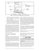
Страница 18: ...sed 2 Extend the vent pipe through the wall approximately I and seal the area be tween the wall and pipe 3 Apply couplings to the vent pipe on the interior and exterior sides of the wall to insure the pipe can not be pushed or pulled through the wall 4 Insure the combustion air inlet pipe has a 90 degree termination elbow and is pointing downward as shown in Figures 19 20 Note that a combustion ai...

Страница 19: ...ough the left side panel the right side panel or through the left or right hole on the bottom panel See Figure 21 Ensure that the flexible drain hose is not kinked The condensate should drain from the plastic collector box location A in Figure 21 as drop lets or a small stream If you notice the furnace has operated for more than 5 minutes without draining or the red status light on the control boa...

Страница 20: ...ace All gas piping must be installed in compliance with local codes and utility regulations Some local regulations require the installation of a manual main shut offvalve and ground joint union exter hal to the furnace The shut off valve should be readily accessible for service and or emer gency use Consult the local utility or gas supplier for additional requirements regarding placement of the ma...

Страница 21: ...the appropriate orifice size listed in Table 8 NOTE The density of air decreases with in creasing elevation above sea level This re duces the quantity of combustion air drawn into the furnace under normal operation and requires the unit be derated by using smaller gas orifices or lower manifold pressure I Set the room thermostat to OFF or its lowest temperature setting 2 Turn OFF the main gas supp...

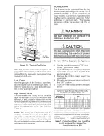
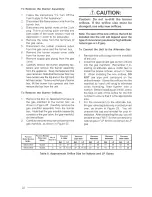
Страница 22: ...nly new orifices Note The size of the new orifices that will be installed into the unit will depend upon the type of conversion sea level or Hgh altitude natural gas or LP gas To Convert the Unit to the Alternate Gas I Remove the orifice bag from the manifold of the unit 2 Install the appropriate gas burner orifices into the gas manifold Remember if in stalling at altitudes above 4 000 feet to ins...

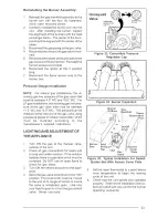
Страница 23: ...e using a pressure gauge or U tube manometer which must be installed according to the manufacturer s supplied instructions LiGHTiNG AND ADJUSTMENT OF THE APPLIANCE I Turn ON the gas at the manual valve outside of the unit 2 Check all gas connections for leaks with a soap and water solution If the solution bubbles there is a gas leak which must be corrected Do NOT use an open flame to check for gas...

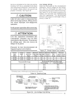
Страница 24: ...In WC Natural Gas 3 5 Propane LP Gas 10 0 Table 9 Manifold Pressure COMPLETING THE CONVERSION I Affix the gas valve conversion label found in the package with the orifices to the unit rating plate 2 Run the appliance through a complete cycle to assure proper operation ELECTRICAL WIRING Genera Electrical connections must be made in accoF dance with all applicable local codes and ordi nances and wit...

Страница 25: ... S assurer du bon fonctionnement de l appareil apr_s tout entretien c _ _ C _ _ BowerOff Til mg 24 V TWIN _1 1 o1 1 _1 _ Figure 27 Blower Speed Tap Location Furnace Cabinet Nominal Maximum Minimum Maximum Minimum Maximum Input Width Electrical Operating Operating Furnace Wire Fuse or Circuit Btuh in Supply Voltage Voltage Amperes Gauge Breaker Amps 60 000 19 75 115 60 1 127 103 9 7 14 15 80 000 19...

Страница 26: ...llation of the VentiiAire Ill or IV follow the instructions provided with the VentilAire kit START UP AND ADJUSTMENTS General Prior to start up verify that I The line voltage power leads are securely connected that the polarity of the con nections is correct and that the furnace is properly grounded 2 The thermostat wires R W Y and G are securely connected to the correct leads on the terminal stri...

Страница 27: ...column for use with natural gas The manifold pressure must be set at I 0 0 in water column for use with LP gas Verifying and Adjusting Temperature Rise Verify that the temperature rise through the furnace is within the range specified on the fur nace rating plate Temperature rises outside the specified range could result in premature heat exchanger failure Place thermometers in the return and supp...

Страница 28: ... Flames should extend from each burner without lifting curling or floating After verifying ignition set the thermostat below room temperature and verify that the burner flame extinguishes completely Replace the front door Verifying Operation of the Supply Air Limit Switch To verify operation of the supply air limit switch make sure that the blower door is in place and that there is power to the fu...

Страница 29: ...perature increases above 145 F This switch protects the plastic flue system and the inducer from over temperature conditions Flame Roll Out Switch This switch pro vides flame roll out protection to the furnace and combustion air inlet pipe It is recommended that the furnace be checked yearly At a minimum this check should include the following items WARNmNG To avoid electric shock personal injury ...

Страница 30: ...flammable vapors and liquids in the vicinity of the furnace Change or replace the air filters monthly during any period when the circulating blower is operating regularly Always replace the doors on the furnace after servicing Do not operate the furnace without all doors and covers in place Avoid operating the furnace when windows and doors are open Be sure that the thermostat is propermy installe...

Страница 31: ...loses When the limit closes the inducer blower is de energized immediately The circulating air blower continues to operate for the speci fied delay factory set at 120 seconds Cooling Mode I On a call for cooling the thermostat closes applying 24 VAC to the G and Y terminals on the furnace control This closes the compressor contactor 2 The furnace control energizes the circu lating blower 115 VAC o...

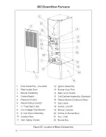
Страница 32: ...Tube 8 LowVoltage Transformer 9 In Line Drain Assembly 10 Junction Box 11 Vent Safety Switch 12 Ignitor Assembly 13 BurnerView Port 14 Main Limit Switch 15 Coil Cabinet Assembly Optional 16 Flame Sensor On Burner Box 17 Gas Valve 18 Switch On Off 19 Blower Inducer 20 Orifice In BurnerBox 21 Aux Limit BurnerBox Figure 29 Location of Major Components 32 ...

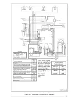
Страница 33: ...n FAULT CONDITION Low Flame Sensor Signal Flame Present STATUS RED LUGHT ON I FLASH 2 FLASHES 3 FLASHES 4 FLASHES 5 FLASHES Continuous OFF FLAME YELLOW LIGHT Continuous Flash ON tf any of the originat wire as supplied with the furnace must be replaced it must be replaced with wiring materiaJ having a temperature rating of at least 105 C Use copper conductors only MOTOR PLUG Factory Wired Heating S...

Страница 34: ...34 ...

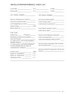
Страница 35: ...ting Manifold Pressure in water column with furnace operating Is there adequate fresh air supply for combustion and ventilation Furnace Input Supply Air Temperature Return Air Temperature Temperature Rise Btuh F F F Are Flue Connections tight Is there Proper Draft Is Vent free from restrictions Is the Filter s secured in place Is the Filter s clean Has the Thermostat been calibrated Is the Thermos...

Страница 36: ...O Fallon MO NORDYNE 708219D 7082t9D Replaces 708219C Specifications and illustrations subject to change without notice and without incurring obligations Printedin US A 04 04 ...

Отзывы: