28
8. Hot Surface Ignition System
Model M1M
SEQUENCE OF OPERATION M1M SERIES
Call for heat: the thermostat calls for heat by energizing the
“W” terminal. The control checks to see the pressure switch
is open. If the pressure switch is closed when the call for heat
occurs, the control will begin to flash “3” on the Status LED
after 10 seconds and wait indefinitely for the pressure switch
to open.
Pressure switch proving: the control energizes the induced
draft motor and waits for the pressure switch to close. If the
pressure switch does not close within 10 seconds of the
inducer energizing, the control will begin to flash “2” on the
Status LED and wait indefinitely for the pressure switch to
close.
Pre-purge: the control runs the inducer for a 45 second pre-
purge time.
HSI warm up: the control energizes the HSI for 30 seconds.
The inducer remains energized.
Ignition activation period: the control energizes the main gas
valve for 6 seconds. The inducer and HSI remain energized.
Flame proving: the control de-energizes the hot surface
ignitor. The gas valve and inducer remain energized. If flame
is present 1 second after HSI de-energizes, the control goes
to blower on delay. If a flame is not present, the control de-
energizes the gas valve and proceeds with ignition retries as
specified below.
Blower on delay: If flame is present, the control energizes the
blower on HEAT speed 30 seconds after the gas valve
opened (24 seconds from HSI off). The gas valve and inducer
remain energized.
Steady heat: Control inputs are continuously monitored to
ensure limit and pressure switches are closed, flame is
established, and the thermostat call for heat remains.
Post purge: When the thermostat demand for heat is satisfied,
the control de-energizes the gas valves. The inducer output
remains on for a 30 second post-purge period.
Blower off delay: The indoor blower motor is de-energized
after a 120 second blower off delay. Blower timing begins
when the thermostat is satisfied.
COMPONENT PARTS
TROUBLESHOOTING
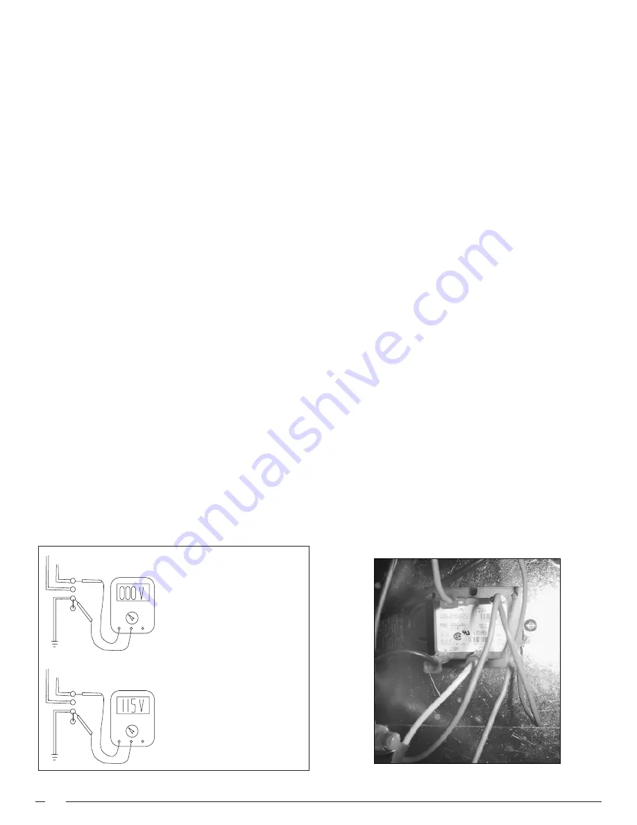
Polarity and Ground
The furnace will not operate if loss of ground occurs. Every
effort should be made at the installation to provide a good
ground. If old 2-wire romex exists it should be replaced with a
2-wire w/ground. A cold water line could be used provided that
the connection or grounding occurs before any di-electric
fittings and provided no plastic pipe is used inside or outside
the building.
Transformer (See Figure 21) – The transformer supplies
control voltage (24 vac) by stepping down the supply (pri-
mary) voltage from 115 vac to 24 vac (secondary voltage).
Transformers are rated by VA. VA is the volt/amp or total
wattage the secondary can handle. When a transformer is
replaced the VA should be of an equal or greater value.
Check-out procedure:
1.
Using a volt/ohmmeter on at least 115 vac scale.
2.
Measure the voltage on the control board terminals
"XFMR" & "NEUTRAL".
3.
If voltage is 115 vac measure the voltage at terminals
marked "24 vac" & "Com" located in the center of the
control board.
4.
If 115 vac is measured at "XFMR" & "NEUTRAL" but no
voltage is present at "24 vac" & "Com" replace transformer.
GROUND
NEUT.
HOT
OK
VOLTS AC
VOLTS DC
OHMS
MICRO
AMPS
Volts
Com
Prep
GROUND
NEUT.
HOT
HOT NEUTRAL
VOLTS AC
VOLTS DC
OHMS
MICRO
AMPS
Volts
Com
Prep
Polarity may be verified as follows:
1. Turn power supply "ON"
2. Using a voltmeter, check for
voltage between the hot (black)
and neutral (white) wire of
supply circuit.
3. Reading should be Line (Supply)
Voltage.
4. Check for voltage between the
neutral (white) wire and ground
wire of the supply circuit.
5. Reading should be zero volts (if
line voltage is read, polarity is
reversed).
6. Double check by checking for
voltage between the hot (black)
wire and ground wire of the
supply circuit.
Figure 22. Polarity and Ground
Picture 11. M1M Transformer


