background image

English 

Owner

s Manual 

ODR-C 


3/8 


Operation 

Velcro or rubber feet 

There is a set of Velcro pads and a set of rubber feet included. Depending on the application, please attach 

the Velcro or the rubber feet. 


 Note: Please keep the screws free so that access to the inside is maintained! 

Connection to a DC power-supply: 

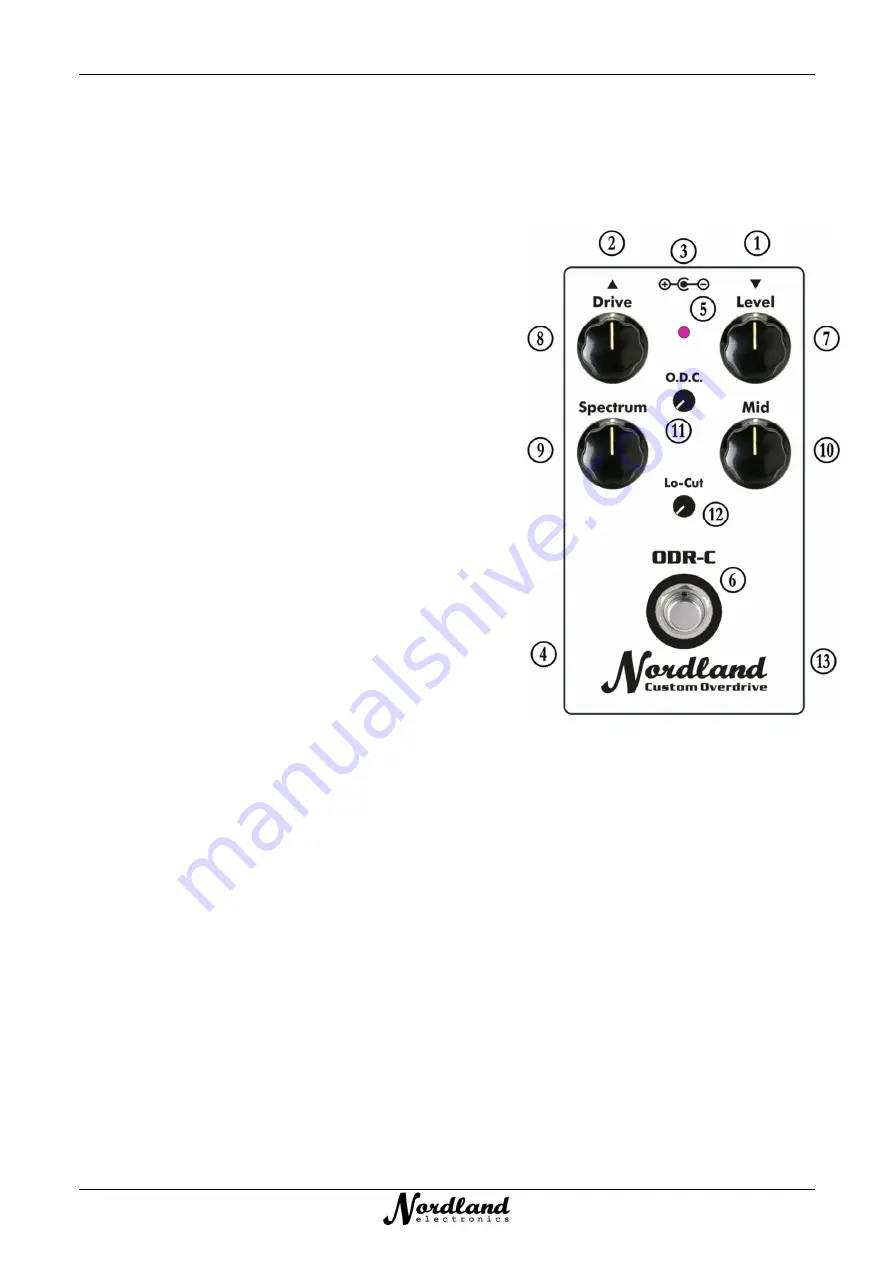
Connect  the  DC-socket 

D

  to  a  standard  power-supply  (hum-

free,  electronically  stabilized!).  The  voltage  must  be  between 

9 V  and  18  V.  Depending  on  the  operating  voltage,  the  device 

requires  between  15 mA  and  25 mA.  The  power-supply  should 

be  able  to  deliver  at  least 50 mA.  The  inner  pole of the  socket 

(5.5 mm / 2.1 mm) is ground, the outer ring must be on plus (+). 

If  the  polarity  is  wrong,  the  built-in  reverse  polarity  protection 

prevents  (to  a  certain  extent)  damage  to  the  ODR-C. 

Nevertheless,  it  should  be  avoided,  since  when  using  other 

devices  on  this  power  supply,  the  positive  contact  on  the 

housing  (usually:  ground)  is  applied.  As  a  result,  touching  or 

wiring  with  another  device  may  cause  a  short  circuit  in  this 

power supply unit and possibly damage it! 

Connection to a 9 V battery: 

After  removing  the  bottom  plate 

E

  (4x  Phillips  screws),  a  9 V 

block  battery  (recommended:  alkaline-manganese)  can  be 

connected  to  the  clip  and  placed  behind  the  foot  switch. 

Depending on the battery, this will last for several hours until it 

has to be replaced.  

For environmental reasons, however, I strongly advise against using batteries!  

Connection 

The  output  signal  from  the  instrument  or  another  effect-device  is  connected  to  the  input  jack 

  with  a 

mono-jack cable (1/4" or 6.3 mm plug). 


Note: When using a stereo-cable, the unit cannot be turned on unless the ring-contact is grounded (GND)! 

At the output -jack 

 a cable to the following device (amplifier, another effect pedal, etc.) is connected.  

Effect On 

The true bypass-switch 

G

 turns the effect on / off. The LED 

F

 lights up when the effect is 

on

. The signal is 

routed from the input-jack, through the footswitch directly to the output-jack. A resistor of 1M0 across this 

signal  is  grounded  to  divert  DC  offset-voltages,  or  vice  versa  capacitors  to  discharge,  which  reduces  the 

switching-noise! 

Before switching on, please make sure that the volume 

H

 is set so low that any impairment or damage of 

any kind (health: hearing, electrical: loudspeakers, amplifiers) is excluded.  


Note: Clicking noises when switching cannot be prevented 100%. Just after connecting to a DC power-supply, it can 

be a little louder when switching over the first few times. It takes a while until the operating values are stable. Then 

it  gets  quieter.  If  the  crackling  is  permanently  too  high,  this  can  also  be  caused  by  the  connected  devices  by  the 

previous or subsequent stage has superimposed some DC voltage (DC-offset)!  

Содержание Custom Overdrive ODR-C

Страница 1: ...English Owner s Manual ODR C ODR C Custom Overdrive Please read this manual carefully After reading keep this document where it will be available for reference ...

Страница 2: ...ies The result is the new ODR C which sounds in the basic sound like my ODR 1 but has many news and quality improvements New Functions A small O D C knob to decrease the amount of overdrive compression technically occurs during the overdrive process Another small Lo Cut knob to control the low frequencies out of the signal A big Mid knob to control the midrange Improvements The built in components...

Страница 3: ...ch Depending on the battery this will last for several hours until it has to be replaced For environmental reasons however I strongly advise against using batteries Connection The output signal from the instrument or another effect device is connected to the input jack with a mono jack cable 1 4 or 6 3 mm plug Note When using a stereo cable the unit cannot be turned on unless the ring contact is g...

Страница 4: ...trum This control J has always been special Unlike other devices on the market called Tone or Treble which prune the signal simply in the treble dull control I use an active electronics which regulates not only the treble from about 1 kHz but likewise the basses around approx 300 Hz so rather the lower middle range Orange The center position is the normal sound In this position the button engages ...

Страница 5: ...gnal component the auditory impression of less overdriving can occur as the density of the signal decreases accordingly Blue Left stop Red Mid Position Orange Right stop So do not be surprised When turning to the right the bass decreases that is so intentional Bonus If the control is turned all the way to the right orange the overdrive about 3 o clock position increases to counteract the reduced d...

Страница 6: ...n the brightness is at a medium brightness level With a small screwdriver the LED brightness N can be set inside to a desired brightness Sound Examples Low Gain Drive Light Overdrive Blues Medium Overdrive Blues Solo Overdrive Heavy Dynamic Rhythm Heavy Compressed Solo ...

Страница 7: ...ids of any kind can damage the device Keep your cat away Do not use harsh detergents If necessary the ODR C should be cleaned with a soft cloth Batteries o Improper handling of batteries can cause them to explode or leak Therefore always observe all safety instructions regarding the batteries o If the device is powered by a battery the decreasing capacity LED will be dimly lit Then the battery sho...

Страница 8: ...English Owner s Manual ODR C 200320 RoHS Copyright 2019 Nordland Electronics Nordland is a registered trademark http nordland electronics com ...

Отзывы: