background image

6

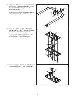
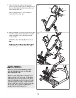
1.

Attach a Foot (42) to the Left Base (1) with an
M4 x 20mm Screw (71). Next, tighten a
Leveling Foot (41) into the Left Base.

Press a 63mm Round Cap (40) onto the Left
Base (1). 

Repeat this step for the Right Base (2).

1

Before beginning assembly, make sure
that you understand the information in
the box above. For help identifying
small parts, see page 5.

1

71

42

2

41

40

Before beginning assembly, carefully read the
following information and instructions:

• Assembly requires two persons.

Because of its weight and size, the inversion
table should be assembled in the location where
it will be used. Make sure that there is enough
clearance to walk around the inversion table as
you assemble it.

Place all parts in a cleared area and remove the
packing materials. Do not dispose of the packing
materials until assembly is completed.

Tighten all parts as you assemble them, unless
instructed to do otherwise. 

As you assemble the inversion table, 

make sure

that all parts are oriented as shown in the
drawings.

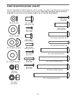
• For help identifying small parts, use the PART

IDENTIFICATION CHART on page 5.

In addition to the included hex key
and grease packets, the following tools (not
included) may be required for assembly:  

• two adjustable wrenches

• one rubber mallet

• one standard screwdriver

• one Phillips screwdriver

Assembly will be more convenient if you have a
socket set, a set of open-end or closed-end
wrenches, or a set of ratchet wrenches.

Make Assembly Easier

This manual is designed to ensure that the
inversion table can be assembled successfully
by almost anyone. However, the inversion table
has many parts, and the assembly process will
take time. Most people find that if they set aside
plenty of time, assembly goes smoothly. 

ASSEMBLY

Содержание Revitalize 30792.0

Страница 1: ...Mon Fri 8 00 until 17 00 EST excluding holidays OR E MAIL US customerservice iconcanada ca USER S MANUAL Visit our website at www proform com new products prizes fitness tips and much more Visit our w...

Страница 2: ...N CHART 5 ASSEMBLY 6 ADJUSTMENT 13 ROTATING ON THE INVERSION TABLE 15 DEVELOPING A PROGRAM 16 PART LIST 18 EXPLODED DRAWING 19 ORDERING REPLACEMENT PARTS Back Cover LIMITED WARRANTY Back Cover TABLE O...

Страница 3: ...tip over 14 Always exercise with a partner Your partner should be ready to return the backrest to the upright position if you cannot complete the rotation 15 If you feel pain or dizziness while exerci...

Страница 4: ...l discs stretch and relax your muscles and temporarily relieve back pain associated with the listed conditions For your benefit read this manual carefully before using the inversion table If you have...

Страница 5: ...lt 53 M10 x 16mm Button Screw 54 M10 x 75mm Button Bolt 57 M10 x 80mm Button Bolt 52 M10 x 53mm Button Bolt 49 M8 x 16mm Button Bolt 61 M5 x 25mm Screw 59 M10 Large Washer 64 PART IDENTIFICATION CHART...

Страница 6: ...dispose of the packing materials until assembly is completed Tighten all parts as you assemble them unless instructed to do otherwise As you assemble the inversion table make sure that all parts are...

Страница 7: ...Base 2 with an M4 x 20mm Screw 71 3 Attach the Support Leg 13 to the Center Base 3 with three M10 x 35mm Button Bolts 53 and three M10 Nylon Locknuts 65 Attach the Base Plate 14 to the Center Base 3...

Страница 8: ...he Left Large Spacer 31 and the Left Frame 4 to the Center Frame 7 with an M10 Nylon Locknut 65 an M10 Large Washer 64 and a 29mm Spacer 48 Then press an 89mm Cap 32 into the Center Frame Repeat this...

Страница 9: ...mm Button Screws 54 9 9 8 54 54 10 Apply a small amount of grease to an M10 x 95mm Button Bolt 73 Pull the Long Adjustment Knob 37 out as far as it will go Insert the bracket on the Backrest Frame 8 i...

Страница 10: ...into the Foot Plate Do not tighten the Screws yet 13 Slide the Lock Frame 11 onto the notched bracket on the Leg Frame 10 and insert the lower end of the Lock Frame into the slot in the Foot Plate 19...

Страница 11: ...Frame 11 Next press a 19mm Round Cap 45 into the round tube and attach the Round Cap with an M4 x 15mm Screw 58 Attach the other Front Ankle Brace 22 in the same way 34 18 Holes Holes 34 58 58 45 15...

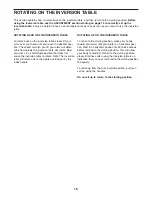
Страница 12: ...other Handle 12 in the same way Make sure that all parts are properly tight ened before you use the inversion table 18 65 50 52 12 12 65 4 56 55 9 35 13 65 10 WARNING HOW TO LOCK THE INVERSION TABLE F...

Страница 13: ...t Frame 8 first pull the Long Adjustment Knob 37 out as far as it will go Move the Backrest Frame and engage the Long Adjustment Knob into the desired hole in the bracket on the Backrest Frame Try the...

Страница 14: ...will go and turn the Index Handle until the arrow on top of the Index Handle points to the desired degree setting Then release the Index Handle make sure that the Index Handle is fully engaged 11 33 1...

Страница 15: ...the inversion table will rotate Rest your arms in a comfortable position that does not cause the inversion table to rotate Note The inversion table will rotate only to the degree setting set by the i...

Страница 16: ...le as described under the BEGINNER PROGRAM Increase the angle to which the inversion table can rotate as it is comfortable Adjust the index handle to allow the inversion table to rotate to up to 60 a...

Страница 17: ...17 NOTES...
Страница 18: ...ut 44 2 32mm Round Cap 45 4 19mm Round Cap 46 2 16mm Spacer 47 2 Pivot Bushing 48 2 29mm Spacer 49 2 M10 x 53mm Button Bolt 50 12 M10 Curved Washer 51 4 M10 x 85mm Button Bolt 52 10 M10 x 80mm Button...

Страница 19: ...0 32 33 69 39 38 40 40 41 41 42 42 42 74 37 44 44 46 45 45 45 45 47 48 48 47 39 36 65 65 52 52 52 52 52 52 65 73 55 56 55 56 54 57 58 58 58 58 75 58 49 71 71 59 59 60 61 58 50 50 50 50 50 50 50 62 62...

Страница 20: ...oduct caused by or attributable to freight damage abuse misuse improper or abnormal usage or repairs not provided by an ICON authorized service center products used for commercial or rental purposes o...

Отзывы: