background image

20

Inspect and tighten all parts of the exercise cycle reg-
ularly. Replace any worn parts immediately. 

To clean the exercise cycle, use a damp cloth and a
small amount of mild soap. 

Important: To avoid

damage to the console, keep liquids away from
the console and keep the console out of direct
sunlight.

BATTERY REPLACEMENT

If the console display becomes dim, the batteries
should be replaced; most console problems are the
result of low batteries. See assembly step 7 on page
8 for replacement instructions.  

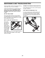
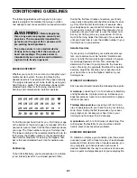
HOW TO LEVEL THE EXERCISE CYCLE

After the exer-
cise cycle has
been moved to
the location
where it will be
used, make sure
that both ends of
the front stabiliz-
er are touching
the floor. If the
exercise cycle
rocks slightly during use, turn one or both of the level-
ing feet under the front stabilizer until the rocking
motion is eliminated. 

HANDGRIP PULSE SENSOR TROUBLESHOOTING

If the handgrip pulse sensor does not function properly,
see step 5 on page 12.

HOW TO MOVE THE EXERCISE CYCLE

To move the exercise cycle, hold the handle on the
rear stabilizer and carefully lift it until the exercise
cycle can be moved on the front wheels. Carefully
move the exercise cycle to the desired location and
then lower it.

MAINTENANCE AND TROUBLESHOOTING 

Handle

Wheel

Leveling

Foot

Содержание NTC3015.0

Страница 1: ...l No Visit our website at www nordictrack com new products prizes fitness tips and much more QUESTIONS As a manufacturer we are com mitted to providing complete customer satisfaction If you have questions or if parts are damaged or missing PLEASE CONTACT OUR CUSTOMER SER VICE DEPARTMENT DIRECTLY CALL TOLL FREE 1 888 825 2588 Mon Fri 6 a m 6 p m MST ON THE WEB www nordictrackservice com ...

Страница 2: ...ASSEMBLY 5 HOW TO OPERATE THE EXERCISE CYCLE 9 MAINTENANCE AND TROUBLESHOOTING 20 CONDITIONING GUIDELINES 21 PART LIST 22 EXPLODED DRAWING 23 HOW TO ORDER REPLACEMENT PARTS Back Cover LIMITED WARRANTY Back Cover NordicTrack is a registered trademark of ICON IP Inc ...

Страница 3: ...rotection 9 The exercise cycle should not be used by persons weighing more than 250 pounds 10 The pulse sensor is not a medical device Various factors including the user s move ment may affect the accuracy of heart rate readings The pulse sensor is intended only as an exercise aid in determining heart rate trends in general 11 Always keep your back straight when using the exercise cycle do not arc...

Страница 4: ...se cycle If you have questions after reading this manual see the front cover of this manual To help us assist you please note the product model number and serial number before call ing The model number is NTC3015 0 The serial num ber can be found on a decal attached to the exercise cycle see the front cover of this manual Before reading further please familiarize yourself with the parts that are l...

Страница 5: ...awing is the key number of the part from the PART LIST on page 22 The number following the paren theses is the quantity needed for assembly Note Some small parts may have been pre attached If a part is not in the parts bag check to see if it has been pre attached M6 x 8mm Button Screw 59 2 M8 x 22mm Button Screw 54 6 M4 x 16mm Screw 57 6 M4 x 22mm Screw 60 2 M4 x 16mm Round Head Screw 80 4 M10 x 9...

Страница 6: ...ame 1 attach the Rear Stabilizer 16 to the Frame with four M8 x 54mm Button Screws 52 and four M8 Split Washers 55 52 16 1 3 5 Make sure the Wire Harnesses do not get pinched and damaged during this step 62 1 3 While another person lifts the front of the Frame 1 connect the Middle Wire Harness 51 to the Lower Wire Harness 43 Next slide the Upright Frame 5 into the Frame Be careful to avoid pinchin...

Страница 7: ... 57 Attach the Right Front Side Shield 14 to the right side of the Upright Frame in the same way Next attach the Left Front Side Shield to the Right Front Side Shield with two M4 x 16mm Screws 57 5 5 14 57 13 4 51 5 71 77 42 6 Pull the Upper Wire Harness 42 up through the Handlebar 3 while inserting the Handlebar into the Upright 2 Be careful to avoid pinching the Upper Wire Harness Attach the Han...

Страница 8: ...75 to the pulse wire on the Console Insert the excess wiring into the Upright 2 Attach the Console 4 to the Handlebar 3 with four M4 x 16mm Round Head Screws 80 Be careful to avoid pinching the wires and wire harnesses 9 Thread an M6 x 8mm Button Screw 59 into the front hole in the Seat Post 8 Next orient the Seat Carriage 11 as shown and slide it onto the Seat Post Thread the other M6 x 8mm Butto...

Страница 9: ...urns to loosen it slide the seat to the desired position and then firmly retighten the knob HOW TO ADJUST THE SEAT POST For effective exer cise the seat should be at the proper height As you pedal there should be a slight bend in your knees when the pedals are in the lowest position To adjust the height of the seat first turn the seat post knob counterclockwise two or three turns to loosen it if t...

Страница 10: ...ur home Using the included stereo audio cable you can connect the exercise cycle to your portable stereo home stereo computer or VCR and play special iFIT com CD and video programs iFIT com CDs and videocassettes are available separately iFIT com programs automatically control the resistance of the pedals and prompt you to vary your pace as a personal trainer coaches you through every step of your...

Страница 11: ...til the entire track is lit The track will then dark en and the indicators will again begin to light in succession The Training Zones bar The Training Zones bar will show the approximate inten sity level of your exer cise The upper display The upper display will show the approximate number of grams of carbs you have burned the approxi mate number of calo ries you have burned the distance you have ...

Страница 12: ... to hold the handgrip pulse sensor the lower display will show your heart rate for up to 30 seconds The display will then show your heart rate along with the other modes If your heart rate is not shown make sure that your hands are positioned as described Be care ful not to move your hands excessively or to squeeze the metal contacts too tightly For opti mal performance clean the metal contacts us...

Страница 13: ...crease your pace When the one of the Too Fast indicators lights decrease your pace When the On Pace indica tor lights maintain your current pace Important The pace settings are intended only to provide motivation Your actual pace may be slower than the pace settings Make sure to exercise at a pace that is comfortable for you When only three seconds remain in the first seg ment of the program both ...

Страница 14: ...le of the target heart rate settings of the pro gram will scroll across the matrix If the second heart rate program P 8 is selected a pulse symbol will appear in the matrix Enter a target heart rate setting If the first heart rate program is selected the maximum target heart rate setting of the program will flash in the lower display If desired press the increase and decrease buttons to change the...

Страница 15: ...m before the program ends Both heart rate programs As you pedal the console will regularly compare your heart rate to the target heart rate setting If your heart rate is too far below or above the target heart rate set ting the resistance of the pedals will automatical ly increase or decrease to bring your heart rate closer to the target heart rate setting The Target Pace guide will prompt you to ...

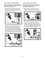
Страница 16: ... Y adapter available at electronics stores Plug the Y adapter into the PHONES jack on your CD player Plug your headphones into the other side of the Y adapter HOW TO CONNECT YOUR PORTABLE STEREO Note If your stereo has an RCA type AUDIO OUT jack see instruction A below If your stereo has a 1 8 LINE OUT jack see instruction B If your stereo has only a PHONES jack see instruction C A Plug one end of...

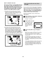
Страница 17: ... adapter Plug the Y adapter into the LINE OUT jack on your stereo HOW TO CONNECT YOUR COMPUTER Note If your computer has a 1 8 LINE OUT jack see instruction A If your computer has only a PHONES jack see instruction B A Plug one end of the audio cable into the jack beneath the console Plug the other end of the cable into the LINE OUT jack on your computer B Plug one end of the audio cable into the ...

Страница 18: ...s 16 to 18 To purchase iFIT com CDs or videocassettes call the toll free telephone number on the front cover of this manual Follow the steps below to use an iFIT com CD or video program Press any button on the console or begin ped aling to turn on the console See step 1 on page 11 Select the iFIT com mode To select the iFIT com mode press the iFIT button The track and the letters iFIT will appear ...

Страница 19: ...system requirements is found on our Web site Follow the steps below to use a program from our Web site Press any button on the console or begin pedaling to turn on the console See step 1 on page 11 Select the iFIT com mode See step 2 on page 18 Go to your computer and start an internet connection Start your Web browser if necessary and go to our Web site at www iFIT com Follow the desired links on...

Страница 20: ...After the exer cise cycle has been moved to the location where it will be used make sure that both ends of the front stabiliz er are touching the floor If the exercise cycle rocks slightly during use turn one or both of the level ing feet under the front stabilizer until the rocking motion is eliminated HANDGRIP PULSE SENSOR TROUBLESHOOTING If the handgrip pulse sensor does not function properly s...

Страница 21: ...exercise Aerobic Exercise If your goal is to strengthen your cardiovascular sys tem your exercise must be aerobic Aerobic exer cise is activity that requires large amounts of oxygen for prolonged periods of time This increases the demand on the heart to pump blood to the muscles and on the lungs to oxygenate the blood For aerobic exercise adjust the intensity of your exercise until your heart rate...

Страница 22: ...rive Belt 48 2 Rear Stabilizer Endcap 49 1 M8 x 52mm Button Bolt 50 2 Flange Screw 51 1 Middle Wire Harness 52 4 M8 x 54mm Button Screw 53 1 Pillow Block 54 6 M8 x 22mm Button Screw 55 14 M8 Split Washer 56 4 M10 x 54mm Button Screw 57 26 M4 x 16mm Screw 58 4 M6 x 13mm Button Screw 59 2 M6 x 8mm Button Screw 60 2 M4 x 22mm Screw 61 1 Small Snap Ring 62 4 6 35mm Spacer 63 4 Wheel Bushing 64 2 M6 Nu...

Страница 23: ...0 42 43 44 66 67 68 48 49 50 50 51 53 54 56 57 58 77 57 57 80 62 63 79 52 79 59 61 69 57 45 46 57 47 71 71 19 64 70 33 31 73 73 72 72 74 75 76 30 29 76 77 71 76 17 60 66 55 55 55 54 54 63 63 63 48 55 55 58 58 58 69 57 57 57 57 57 78 79 79 79 65 41 55 55 81 71 57 EXPLODED DRAWING Model No NTC3015 0 R0505A ...

Страница 24: ...L It is VERY IMPORTANT THAT YOU READ THE MANUAL before operating the Product Remember to do the periodic maintenance requirements specified in the Manual to assure proper operation and your continued satisfaction HOW TO GET PARTS AND SERVICE Simply call our Customer Service Department at 1 888 825 2588 and tell them your name and address and the serial number of your Product They will tell you how...

Отзывы: