Страница 1: ...you have questions or if parts are damaged or missing DO NOT CONTACT THE STORE please contact Customer Care iMPORTANT Please register this product see the limited warranty on the back cover of this manual before contacting Customer Care CALL TOLL FREE 1 888 825 2588 Mon Fri 6 a m 6 p m MT Sat 8 a m 4 p m MT ON THE WEB www nordictrackservice com A UAL ...
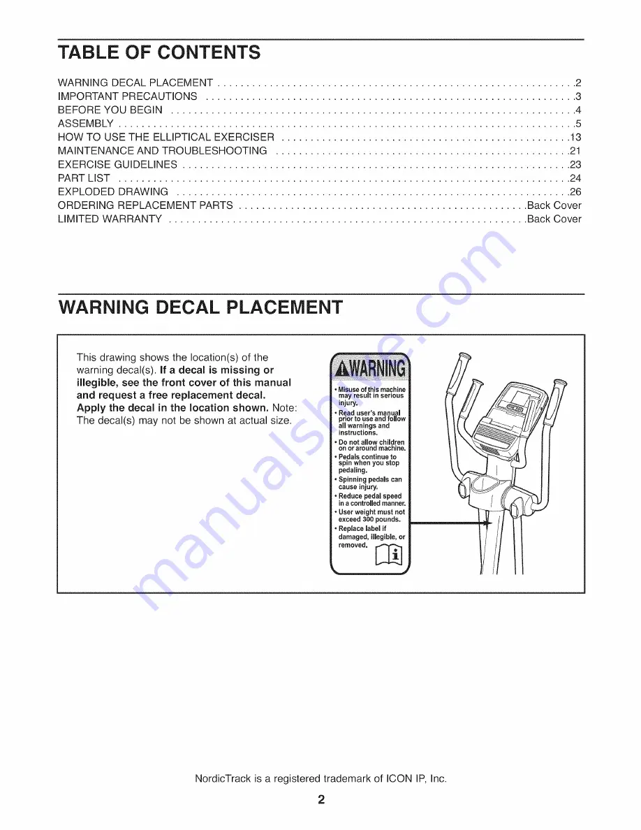
Страница 2: ... illegible see the front cover of this manual and request a free replacement decal Apply the decal in the location shown Note The decal s may not be shown at actual size Misuse of this machine may result in serious injury Read user s manual prior to use and follow all warnings and instructions Do not allow children on or around machine Pedals continue to spin when you stop pedaling Spinning pedals...
Страница 3: ...iMPORTANT PRECAUTIONS 3 ...
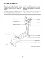
Страница 4: ...eading this manual please see the front cover of this manual To help us assist you note the product model number and serial number before con tacting us The model number and the location of the serial number decal are shown on the front cover of this manual Before reading further please familiarize yourself with the parts that are labeled in the drawing below Handgrip Pulse Sensor Console Upper Bo...
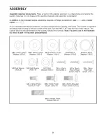
Страница 5: ... key number of the part from the PART LIST near the end of this manual The number following the parentheses is the quantity needed for assembly Note If a part is not in the hardware kit check to see if it has been preassembled M8 x 16mm x 2mm Washer 120 2 M6 Split Washer 112 8 1 M8 x 23mm x 2mm Washer 126 2 M8 Split Washer 103 14 M6 x 12mm Patch Screw 111 8 M8 x 23 5mm x lmm Washer 110 2 M10 Split...
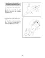
Страница 6: ...r 3 to the Frame with two MIO x 80mm Patch Screws 100 and two MIO Split Washers 123 123 IO0 3 Identify and orient the Rear Stabilizer 4 as shown While another person lifts the Folding Frame 2 attach the Rear Stabilizer 4 to the Folding Frame with two MIO x 80mm Patch Screws 100 and two MIO Split Washers 123 100 123 6 ...
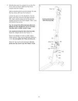
Страница 7: ...ard out of the top of the Upright Then untie and discard the wire tie Tip To prevent the Wire Harness 60 from falling into the Upright 5 secure the Wire Harness with a rubber band or tape Tip Avoid pinching the Wire Harness 60 Insert the Upright 5 into the Frame 1 Attach the Upright 5 with four M8 x 16mm Patch Screws 102 and four M8 Split Washers 103 Do not tighten the Patch Screws yet Slide the T...
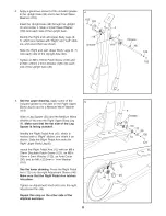
Страница 8: ...e to the axle on the Right Upper Body Leg 6 and to a Medium Wave Washer 119 Slide a Leg Spacer 55 and the Medium Wave Washer 119 onto the Right Upper Body Leg 6 Make sure that the fiat side of the Leg Spacer is facing outward Identify the Right Pedal Arm 12 which is marked with a Right sticker and orient it as shown Slide the Right Pedal Arm onto the Right Upper Body Leg 6 Attach the Right Pedal A...
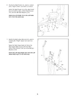
Страница 9: ...12 Attach the Left Pedal 15 to the Left Pedal Arm 13 in the same way 15 12 13 14 111 112 Identify the Right Upper Body Arm 8 which is marked with a Right sticker and orient it as shown Attach the Right Upper Body Arm 8 to the Right Upper Body Leg 6 with three M8 x 16mm Patch Screws 102 and three M8 Split Washers 103 Attach the Left Upper Body Arm 9 to the Left Upper Body Leg 7 in the same way 103 ...
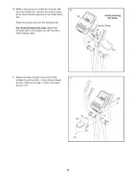
Страница 10: ...exposed to cold temperatures allow it to warm to room temperature before inserting batteries Otherwise you may damage the console displays or other electronic compo nents Remove the screw remove the battery cover insert the batteries into the battery com partment and reattach the battery cover Make sure to orient the batteries as shown by the diagram inside the battery compartment To purchase an o...
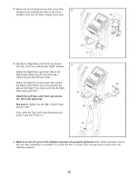
Страница 11: ...s 34 Insert the excess wire into the Console 33 Tip Avoid pinching the wires Attach the Console 33 to the Upright 5 with four M4 x 16mm Screws 93 10 _C Avoid pinching the wires onsole Wires 93 11 Attach the Rear Upright Cover 24 to the Upright 5 with two M4 x 16mm Round Head Screws 106 and an M4 x 19mm Flat Head Screw 117 11 117 106 11 ...
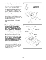
Страница 12: ...ront Leg Cover 30 around the Right Upper Body Leg 6 by pressing the tabs on the Right Front Leg Cover into the Right Rear Leg Cover 29 Attach the Left Rear and Front Leg Covers 31 32 in the same way See step 3 Tighten the four M8 x 16mm Patch Screws 102 Then slide the Top Cover 23 downward and press it over the Frame 1 13 J 31 30 14 Make sure that all parts of the elliptical exerciser are properly...
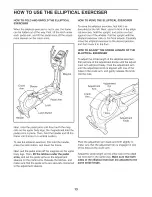
Страница 13: ...tment sleeves HOW TO MOVE THE ELLIPTICAL EXERCISER To move the elliptical exerciser first fold it as described at the left Next stand in front of the ellipti cal exerciser hold the upright and place one foot against one of the wheels Pull the upright until the elliptical exerciser rolls on the front wheels Carefully move the elliptical exerciser to the desired position and then lower it to the flo...
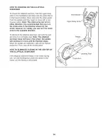
Страница 14: ...owever for variety you can turn the crank arms in the opposite direction To dismount the elliptical exerciser wait until the ped als come to a complete stop Note The elliptical exerciser does not have a free wheel the pedals will continue to move until the flywheel stops When the pedals are stationary step off the highest pedal first Then step off the lowest pedal HOW TO ELIMINATE FLEXING IN THE C...
Страница 15: ... Workout System which enables the console to accept iFit cards containing workouts designed to help you achieve specific fitness goals For example lose unwanted pounds with the 8 week Weight Loss work out iFit workouts control the resistance of the pedals while the voice of a personal trainer coaches you through your workouts iFit cards are available sepa rately To purchase iFit cards go to www iF...
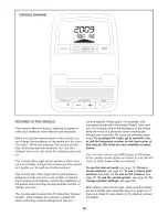
Страница 16: ...d time The lower right display The lower right display can show the your ped aling speed in revolutions per minute rpm and the approximate number of calo ries that you have burned Note When a calorie goal workout is selected the display will count down the number of calories to be burned The display also shows your heart rate when you use the handgrip pulse sensor see step 5 on page 17 Th r I disp...
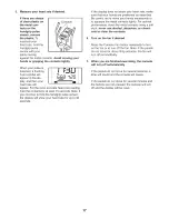
Страница 17: ...seconds If the display does not show your heart rate make sure that your hands are positioned as described Be careful not to move your hands excessively or to squeeze the metal contacts tightly For optimal performance clean the metal contacts using a soft cloth never use alcohol abrasives or chemi cals to clean the contacts 6 Turn on the fan if desired Press the Coolaire Fan button repeatedly to t...
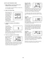
Страница 18: ... resistance level for the cur rent segment At the end of each segment of the workout a series of tones will sound and the next segment of the profile will begin to flash If a different resis tance level is programmed for the next segment the resistance level will appear in the display for a few seconds to alert you The resistance of the pedals will then change If the resistance level for the curre...
Страница 19: ...vel for the cur rent segment At the end of each segment of the workout a series of tones will sound and the next segment of the profile will begin to flash If a different resis tance level is programmed for the next segment the resistance level will appear in the display for a few seconds to alert you The resistance of the pedals will then change If the resistance level for the current segment is ...
Страница 20: ...e you exercise plug the audio cable into the jack on the console and into a jack on your MP3 player or CD player make sure that the audio cable is fully plugged in Next press the play button on your MP3 player or CD player Adjust the volume level using the volume con trol on your MP3 player or CD player or press the Volume increase and decrease buttons on the con sole HOW TO CHANGE CONSOLE SETTING...
Страница 21: ...hen you use the handgrip pulse sensor see step 5 on page 17 HOW TO ADJUST THE REED SWITCH If the console does not display correct feedback the reed switch should be adjusted To adjust the reed switch you must first remove the Top Shield 20 Using a flat screwdriver release the tabs on the front and rear of the Top Shield and then remove the Top Shield 20 Next locate the Reed Switch 69 Loosen but do...
Страница 22: ...bs on the front and rear of the Top Shield 20 and then remove the Top Shield Loosen the Pivot Screw 97 Then tighten the Belt Adjustment Screw 85 until the Drive Belt 38 is tight 20 106 106 124 124 106 When the Drive Belt 38 is tight tighten the Pivot Screw 97 Then reattach the left shield and the top shield Next remove the M4 x 16mm Round Head Screws 106 and the M4 x 42mm Screws 124 from the Right...
Страница 23: ... energy if your goal is to burn fat adjust the intensity of your exercise until your heart rate is near the lowest number in your training zone For maximum fat burning exercise with your heart rate near the middle number in your training zone Aerobic Exercise if your goal is to strengthen your cardiovascular system you must perform aerobic exercise which is activity that requires large amounts of ...
Страница 24: ...2 Adjustment Knob 46 2 Adjustment Sleeve 47 4 Sleeve Bushing 48 1 Upright Axle 49 2 Latch Housing 50 2 Latch Key No Qty 51 2 52 2 53 2 54 4 55 2 56 2 57 2 58 4 59 1 6O 1 61 1 62 1 63 1 64 2 65 1 66 1 67 1 68 1 69 1 70 1 71 1 72 1 73 1 74 1 75 2 76 2 77 1 78 1 79 1 80 1 81 1 82 1 83 1 84 1 85 1 86 12 87 2 88 1 89 4 90 1 91 1 92 1 93 7 94 2 95 1 96 1 97 1 98 2 99 1 100 4 Description Latch Spring Lat...
Страница 25: ...mm Patch Screw 126 2 112 8 M6 Split Washer 127 2 113 2 M8 x 18mm Button Screw 128 2 114 2 M8 x 32mm Washer 115 2 Large Wave Washer Large Snap Ring M4 x 19mm Flat Head Screw Small Wave Washer Medium Wave Washer M8 x 16mm x 2mm Washer M8 x 23mm Shoulder Patch Screw 3 8 x 1 Flange Screw M10 Split Washer M4 x 42mm Screw M4 x 42mm Flat Head Screw M8 x 23mm x 2mm Washer Long C pin Short C pin User s Man...
Страница 26: ...102 102 33 103 103 15 54 102 93 106 103 54 _ 29 55 25 93 30 102 i i 126 102 103 103 102 119 m X r 0 0 m 0 m Z 63 I 0 m Z 0 Z 4 m r o t_ o 0 o r o o r o ...
Страница 27: ... 4 86 16 124 38 37 4 100 61 18 104 106 22 106 107 108 83 64 63 84 36 100 104 86 rT X r 0 rT m Z 0 W J 0 O m Z 0 in Z 4 1 r o o 0 o r o o r o 3 ...
Страница 28: ...onsible for a min imal handling charge For in home service the customer will be responsible for a minimal trip charge This warranty does not extend to any damage to a product caused by or attributable to freight damage abuse misuse improper or abnormal usage or repairs not provided by an ICON authorized service center to products used for commercial or rental purposes or as store display models or...