


Hardware description
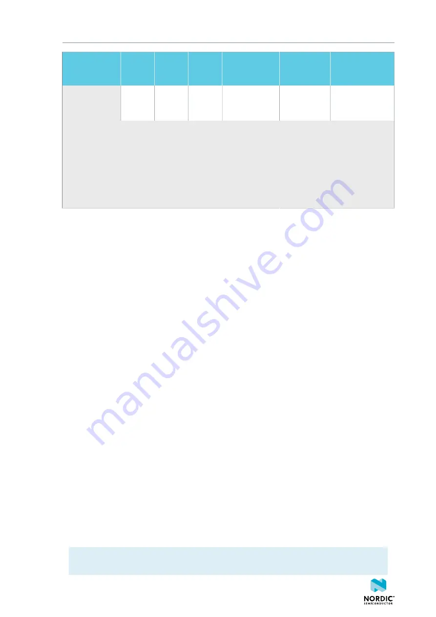
Name
nRF52
control
GPIO
Hardware
default
nRF9160
GPIO
External
Default
Optional
P0.25
(nCS)
P6_pin5 (D18) /
P25_pin20
(TRACEDATA3)
–
EXT_FLASH nCS
1
For the location of connectors, see
Figure 5: nRF9160 DK (PCA10090), front view
on page 12.
2
When the I/O expander is enabled, the interrupt line from the I/O expander shares the same GPIO as
Button 1.
3
Pins are shared with TRACE, and when TRACE functionality is to be used, make sure that the nRF52
control GPIO is in
Hardware default
state.
4
Solder bridge and test point are available and so functionality can be maintained by manually
connecting the signal to a GPIO of choice even when TRACE is in use.
Table 4: Board control routing
Name
The name to be used when referring to this signal path and the configuration needed to control it.
nRF52 control GPIO
The GPIOs on nRF52840 that are used to control the analog switches.
Hardware default
The default logic level of the control signal if pin is not driven.
nRF9160 GPIO
The GPIOs on nRF9160 that can be configured.
External
The connector and pin with permanent routing of the nRF9160 GPIO, not affected by the board
controller.
Default
The default connection for the nRF9160 GPIO if the nRF52 control GPIO pins are not driven
(Hardware default logic level).
Optional
The optional connection for the nRF9160 GPIO if the nRF52 control GPIO pins are driven to the
opposite logic level than the hardware default.
The setup described as Default in the table above is active if all the GPIOs on nRF52840 listed as nRF52
control GPIO are not driven or driven according to the hardware default setting. There are pull resistors on
the switch control lines, and therefore, Default can also be received if the control lines from the nRF52840
are not driven. If the optional routing is desired, the nRF52840 control GPIO pins must be set as outputs
and driven high.
The nRF52840 SoC is preprogrammed with firmware that provides a control setting. This might not be the
same as the hardware default. Configurable code examples for the nRF52840 SoC allowing to change the
board routing can be found in the nRF Connect SDK. After the changes are done, the new program must
be compiled and programmed to the nRF52840. See the nRF Connect SDK documentation on
for information on changing the configuration.
Note:
To program and debug the nRF52840 SoC, nRF52 needs to be selected on the
PROG/DEBUG
SW10
switch (
SW5
for v0.9.0 and earlier).
4418_1216
22