background image

Owner’s Manual  16

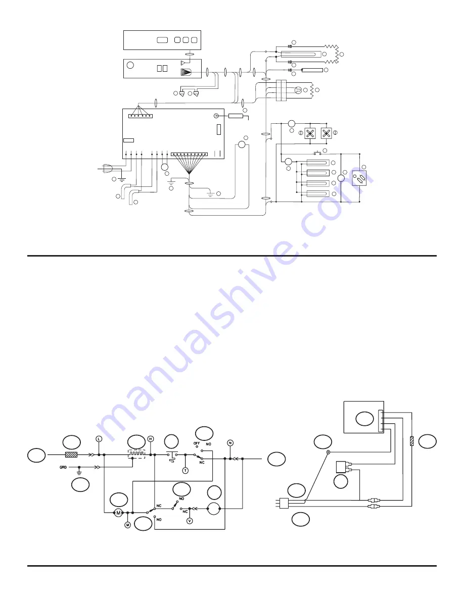
The parts of the ice maker wiring pictorial and diagram are (See Art01500):

1..................................................................................................................................................................................120V AC Hot / smooth 

2..............................................................................................................................................................................120 VAC Neutral / ribbed

3...............................................................................................................................................................................................

Ground screw 

4................................................................................................................................................................................................

Thermal fuse

5....................................................................................................................................................................................

Solenoid water valve 

6......................................................................................................................................................................................................

Ice maker

7.................................................................................................................................................................................................. Mold heater 

8................................................................................................................................................................................................... Thermostat

9..............................................................................................................................................................................................

Shut off switch 

10....................................................................................................................................................................................................Fill switch

11 .................................................................................................................................................................................................Hold switch 

12.......................................................................................................................................................................................................... Motor

Ice Maker Wiring Pictorial and Diagram (Optional)

RD/RG

A   TEMPERATURE SWITCH / INTERRUPTRUR DE TEMPÉRATURE

B   AC HEATERS / ÉLÉMENTS CHAUFFANT CA

C   THERMISTOR / THERMISTANCE

D   LIGHT / LAMPE

E   DIVIDER HEATER / ELEMENT DE CLOISON

F   DOOR CONTACTS / CONTACTS DE PORTE

G   DOOR SWITCHES / INTERRUPTES DE PORTE

H   GAS VALVE / ROBINET DE GAZ

      FANS / VENTILATEURS

J    IM WATER LINE HEATER / CHAUFFERETTE DU YUYAU D’EAU

           DE LA MACHINE À GLAÇONS

K   WATER VALVE HEATER / CHAUFFERETTE DU ROBINET  D’EAU

L    DISPENSER WATER LINE HEATER / CHAUFFERETTE DU TUYAU

           D’EAU DU DISTRIBUTEUR 

*

*

*

*

*

*

*

*

*

M   DISPENSER WATER VALVE HEATER / CHAUFFERETTE DU

           ROBINET D’EAU DU DISTRIBUTEUR

N   DISPENSER VALVE / ROBINET DU DISTRIBUTEUR

0    FAN TEMPERATURE SWITCH / INTERRUPTRUR DE TEMPÉRATURE

           VENTILATEUR

P   TEMPERATURE SWITCH / INTERRUPTRUR DE TEMPÉRATURE

Q   DISPENSER SWITCH / INTERRUPTEUR DU DISTRIBUTEUR

R   DISPENSER LIGHT / LAMPE DU DISTRIBUTEUR

S   IGNITER / ALLUMEUR

T   CHASSIS GROUND / MASSE DU CHASSIS

U   FLAPPER HEATER / ÉLÉMENT CHAUFFANT À CLAPET

V   FLAPPER HOUSING GROUND /  MASSE LOGEMENT À CLAPET

   - OPTIONAL / FACULTATIF

*

*

1   SWITCHED 12VDC / COMMUTÉ 12VCD

2   FUSED CONTINUOUS 12VDC/ CONTINU

         FONDU 12VCD

3   COMMUNICATIONS / COMMUNICATIONS

4   DISPLAY GROUND / AFFICHAGE LA TERRE

5   AUXILIARY GROUND / MASSE AUXILIAIRE 

6   AUX12VDC / AUXI12VCD

7   D12VDC / DE C12VCD

8   GAS VALVE +12VDC / ROBINET

         DE GAZ +12VCD

F1  5 AMP DC FUSE / FUSIBLE DE 5 AMPERES CD

F2  8 AMP AC FUSE / FUSIBLE DE 5 AMPERES CA

Art01770

5

L1

L2

P1

1

7

5

OVERLAY/REVÊTRMENT

DISPLAY BOARD/

CARTE D’AFFICHAGE

POWER BOARD/ PANNEAU D’ALIMENTATION

+12VDC/VCD

G

G

4

P2

T1

S

AMP

8 AMP

AC_HT_H

I

LIMIT_IN

LIMIT_OUT

AC_HT_LO

AC_HT_H

I

AC_HT_LO

GND

12VD

C

T

B

B

A

11

T

8

-12VDC/VCD

H

7

M

L

K

J

N

R

P

Q

O

1

6

2

D

C

3

2

4

1

1

E

U

F

F

6

1

10

1

F

V

T

F2

F1

Art01500

109

110

111

114

115

N

G

L

44

GRN / VERT

BRN / BRUN

WHT / BLANC

BLK / NOIR

NEUTRAL (RIBBED) /

NEUTRE (À NERVURES) 

WHT / BLANC

HOT(SMOOTH)/ 

CHAUD (PLAT)

G

RN

 / 

VE

RT

109

112

116

120

119

96

118

44

117

110

111

Содержание 121X AC Series

Страница 1: ...ot store or use gasoline or other flammable vapors and liquid in the vicinity of this or any other appliance NORCOLD Inc P O Box 4248 Sidney OH 45365 4248 Part No 632264A 11 07 English Norcold Customer Support Dept Telephone 800 543 1219 Fax 937 497 3183 Web Site www norcold com Owner s Manual for the 121X AC series of RV Refrigerators The letter X in the model numbers above stands for a letter or...

Страница 2: ...lves 5 Interior light 6 Door alarm 6 Moisture reduction heater 6 Temperature control system 6 Backup operating system 6 Temperature switch monitor 7 Operating the Refrigerator Controls 7 Control panel 7 Ice Maker Optional 8 Ice maker operation 8 Refrigerator Care Checklist 9 Defrosting 9 Cleaning12 Interior 10 Drip tray 10 Metal doors 11 Door Sealing 11 Refrigerator Storage 11 Refrigerator Mainten...

Страница 3: ...y liquids near electrical outlets connections or the refrigerator components Many liquids are electrically conductive and can cause a shock hazard electrical shorts and in some cases fire The refrigerator cooling system is under pressure Do not try to repair or to recharge a defective cooling system The cooling system contains sodium chromate The breathing of certain chromium compounds can cause c...

Страница 4: ... operate the storage latch see Art00991 open each door about 1 2 inch hold the door handle in the open position and push the storage latch 55 into the cutout 56 of the strike plate Do not use the storage latch as a travel latch because the doors will not be fully closed Movable door seal The movable door seal 134 is located on the left door of the fresh food compartment See Art01109 It provides th...

Страница 5: ...the drawer NOTE Do not wash the drawer or divider in a dishwasher The drawer and divider are not dishwasher safe Door bins You may put the door bins 52 of the freezer and fresh food compartment in a location that best meets your needs See Art01114 To remove the bins lift them over the locator and pull them forward To install the bins push them onto the locator NOTE Do not wash the door bins in a d...

Страница 6: ...f the freezer compartment and on the movable door seal The heaters operate only when the refrigerator is ON and the DC power is sufficient The heater in the movable door seal also only operates when the left door of the fresh food compartment is closed Temperature control system Although the refrigerator is not frost free it is made to limit frost on the cooling fins At regular intervals the tempe...

Страница 7: ...e setting the numbers 1 9 show in the center display 33 The number 9 is the coldest temperature setting Push and hold the SET TEMP button and the temperature setting changes Release the SET TEMP button when the temperature setting that you wish appears After ten seconds the temperature setting will go out and only a green power ON light remains NOTE If you open the door s too often the temperature...

Страница 8: ...aking ice The ice maker operates on Cold potable water at a pressure of 15 psi 125 psi 120 Volts AC 108 VAC min 132 VAC max Ice maker operation 1 Make sure the ice maker AC power cord is plugged into a receptacle 2 Open the water shut off valve of the vehicle NOTE Make sure that the ice maker arm can move freely and does not touch the frozen foods in the freezer 3 Push the ice maker arm down to th...

Страница 9: ...the refrigerator Remove the drain hose from the drip cup at the rear of the refrigerator Put the drain hose into a half gallon or larger container to capture water Refrigerator Care Checklist Your refrigerator will give you years of trouble free service if you do these simple checks every three to six months Keep the food compartment and the freezer clean See Cleaning Defrost the refrigerator as n...

Страница 10: ...gerator Make sure that the drip tray is empty of water Pull the drip tray out of the drain hose Pull the drip tray forward to remove from the slots in the refrigerator cabinet Clean the drip tray Cleaning Put dry towels etc inside the refrigerator and freezer to absorb melted frost CAUTION High temperatures can cause the inside surfaces of the refrigerator to warp or melt Do not use pans of HOT wa...

Страница 11: ...the refrigerator is stored for an extended seasonal period of time Defrost and clean the interior of the refrigerator Close the doors with the storage latch If the refrigerator is stored for an extended period of time before start up Make sure there are no obstructions in the vents the ventilation air pathway or the flue area Push the drip tray back into the slots in the refrigerator cabinet Push ...

Страница 12: ...e water solenoid valve and the water supply line can occur 1 Remove the tape and plastic bags from the end of the water supply line the end of the ice maker water line and the water solenoid valve 2 Connect the ice maker water line to the water solenoid valve 3 Connect the garden hose adapter to the water solenoid valve 4 Push the ice maker arm down into the ON position 5 Open the vehicle water su...

Страница 13: ...ng flanges on the front of the refrigerator 5 Remove the screws from the mounting flange at the rear of the refrigerator 6 Remove the refrigerator from the opening Reinstall the Refrigerator Your dealer or Norcold authorized service center must do this procedure 1 Push the refrigerator completely into the enclosure 2 Install the screws in the mounting flange at the rear of the refrigerator 3 Insta...

Страница 14: ...That the battery charging equipment of the vehicle is operational That the AC DC converter is operational if applicable See your dealer or Norcold authorized service center Close the door Check That the refrigerator is plugged into a serviceable outlet That the fuse or circuit breaker is intact That the vehicle generator is operational if applicable See your dealer or Norcold authorized service ce...

Страница 15: ...d 5 Auxilliary ground 6 Auxilliary 12 VDC 7 Divider 12 VDC 8 Gas valve 12 VDC F1 5 Amp DC fuse F2 8 Amp AC fuse Art01769 GND 12VDC AC_HT_HI F2 P2 1 10 2 L1 L2 YL JN BK NR YL JN BK NR AC_HT_LO 120 VAC 120 VCA 3 TEMP T1 12 VDC VCD P1 4 1 2 3 12 VDC VCD WH BC WH BC WH BC WH BC OR OR POWER BOARD PANNEAU D ALIMENTATION ON OFF OVERLAY REVÊTRMENT MODE DISPLAY BOARD CARTE D AFFICHAGE 8 AMP AC_HT_LO AC_HT_...

Страница 16: ... VENTILATEUR P TEMPERATURE SWITCH INTERRUPTRUR DE TEMPÉRATURE Q DISPENSER SWITCH INTERRUPTEUR DU DISTRIBUTEUR R DISPENSER LIGHT LAMPE DU DISTRIBUTEUR S IGNITER ALLUMEUR T CHASSIS GROUND MASSE DU CHASSIS U FLAPPER HEATER ÉLÉMENT CHAUFFANT À CLAPET V FLAPPER HOUSING GROUND MASSE LOGEMENT À CLAPET OPTIONAL FACULTATIF 1 SWITCHED 12VDC COMMUTÉ 12VCD 2 FUSED CONTINUOUS 12VDC CONTINU FONDU 12VCD 3 COMMUN...

Страница 17: ...TÉ Ne pas entreposer ni utiliser d essence ni d autres liquides ou vapeurs inflammables près de ce réfrigérateur ou de tout autre appareil ménager NORCOLD Inc Norcold Service à la clientèle P O Box 4248 Téléphone 800 543 1219 Sidney OH 45365 4248 Télécopieur 937 497 3183 Site Internet www norcold com Part No 632264A 11 07 Français Manuel de l utilisateur propriétaire pour la série 121XAC de réfrig...

Страница 18: ...6 Alarme de porte 6 Système de réduction de l humidité 6 Système de régulation de température 6 Système de secours 6 Dispositif de surveillance de l interrupteur de température 7 Commandes du réfrigérateur 7 Panneau de commande 7 Machine à glaçons option 8 Fonctionnement 8 Liste des opérations d entretien courant 9 Dégivrage 9 Nettoyage 10 Intérieur 10 Plateau de dégivrage 10 Portes métalliques 11...

Страница 19: ...tutifs du réfrigérateur Beaucoup de liquides sont conducteurs et peuvent causer un choc électrique des courts circuits et éventuellement provoquer un incendie Votre réfrigérateur Le système de refroidissement du réfrigérateur est sous pression Ne pas tenter de réparer ou de recharger un système de refroidissement défectueux Le système contient du chromate de sodium L inhalation de certains composé...

Страница 20: ...frigérateur est arrêté pour une longue période Pour utiliser le dispositif de blocage pendant le stockage se reporter à Art00991 entrouvrir chaque porte d environ pouce maintenir la porte entrouverte et pousser le verrou 55 dans l ouverture 56 de la platine Ne pas utiliser le dispositif de blocage pour le stockage comme verrou pendant le déplacement du véhicule parce que les portes ne seront pas c...

Страница 21: ...rte Les casiers de porte 52 du compartiment de conservation des denrées fraîches et des compartiments basse température peuvent être déplacés pour satisfaire les besoins de chaque utilisateur se reporter à Art01114 Pour enlever un casier le soulever au dessus du repère de positionnement et le tirer vers l avant Le pousser en place dans les nouveaux repères de positionnement REMARQUE Ne pas nettoye...

Страница 22: ...er la porte pour arrêter l alarme Système de réduction de l humidité Le réfrigérateur est équipé d un système de chauffage qui empêche la formation d humidité sur la paroi centrale entre les deux portes des compartiments basse température et sur le joint de porte mobile Ce système de chauffage ne fonctionne que lorsque le réfrigérateur est en route et que l alimentation en courant continu est suff...

Страница 23: ...correspondant à la température choisie apparaît L affichage de la température s éteint après dix secondes et seul le voyant vert ON de mise sous tension reste allumé Au bout de dix secondes le paramètre de température s éteint et seul le voyant d alimentation vert ON MARCHE reste allumé Le système de secours peut congeler ou dégeler les denrées se trouvant dans les compartiments basse température ...

Страница 24: ...e la machine à glaçons Eau potable froide à une pression comprise entre 15 et 125 lb po2 120 V c a 108 V mini 132 V maxi Fonctionnement 1 S assurer que le cordon d alimentation en courant alternatif de la machine à glaçons blanc est branché dans une prise de courant 2 Ouvrir le robinet d arrêt d eau du véhicule REMARQUE S assurer que le bras de la machine à glaçons peut se déplacer librement et n ...

Страница 25: ...rigérateur REMARQUE Le dégivrage rend beaucoup d eau dans le réfrigérateur Retirer le tuyau de vidange de la cuvette d égouttage à l arrière du réfrigérateur Placer le tuyau de vidange dans un récipient d au moins un demi gallon pour récupérer l eau Liste des opérations d entretien courant Le réfrigérateur peut fonctionner pendant de nombreuses années sans aucun problème si les opérations simples ...

Страница 26: ...ateau de dégivrage ne contient plus d eau Retirer le plateau de dégivrage du tuyau de vidange Tirer sur le plateau de dégivrage pour le sortir des fentes de la caisse du réfrigérateur Nettoyer le plateau de dégivrage Nettoyage Placer des serviettes sèches etc à l intérieur du réfrigérateur et du congélateur pour absorber le givre fondu AVERTISSEMENT Des températures élevées peuvent entraîner la di...

Страница 27: ...de d arrêt prolongé hors saison d utilisation Dégivrer et nettoyer l intérieur du réfrigérateur Fermer les portes avec le verrou de stockage Avant de remettre en route le réfrigérateur après une période d arrêt prolongé S assurer de l absence d obstructions aux bouches de ventilation passages d air de ventilation ou conduit de fumée Période d arrêt prolongé du réfrigérateur Pousser le plateau de d...

Страница 28: ... de l électrorobinet d eau la résistance de la chaufferette du tuyau d eau 5 Vidanger toute l eau du tuyau d arrivée d eau et du tuyau d eau de la machine à glaçons 6 Placer l extrémité du tuyau d arrivée d eau l extrémité du tuyau d eau de la machine à glaçons et l électrorobinet d eau individuellement dans un sac en plastique propre 7 Fermer à l aide de ruban adhésif chacun des sacs en plastique...

Страница 29: ...eur et inférieur à l avant du réfrigérateur 5 Enlever les vis du rebord de montage à l arrière du réfrigérateur 6 Sortir le réfrigérateur de son logement Remontage du réfrigérateur Cette opération doit être effectuée par le concessionnaire ou un Centre d entretien autorisé Norcold 1 Pousser le réfrigérateur à fond dans le logement 2 Installer les vis par le rebord de montage à l arrière du réfrigé...

Страница 30: ...ur c a c c est opérationnel s il existe Entrer en rapport avec le concessionnaire ou la Centre d entretien autorisé Norcold Fermer la porte Verifier que le réfrigérateur est branché dans une prise qui fonctionne le fusible ou le disjoncteur du véhicule est intact la génératrice du véhicule est opérationnelle si elle existe Entrer en rapport avec le concessionnaire ou la Centre d entretien autorisé...

Страница 31: ...ommuté 12 V c d 2 Continu fondu 12 V c d 3 Communications 4 D affichage la terre 5 Auxiliaire la terre 6 Auxiliaire 12 V c d 7 Séparateur 12 V c d 8 Robinet de gaz 12 V c d F1 Fusible 5 A c d F2 Fusible 8A c a A TEMPERATURE SWITCH INTERRUPTRUR DE TEMPÉRATURE B AC HEATERS ÉLÉMENTS CHAUFFANT CA C THERMISTOR THERMISTANCE Art01769 GND 12VDC AC_HT_HI F2 P2 1 10 2 L1 L2 YL JN BK NR YL JN BK NR AC_HT_LO ...

Страница 32: ...DU DISTRIBUTEUR 0 FAN TEMPERATURE SWITCH INTERRUPTRUR DE TEMPÉRATURE VENTILATEUR P TEMPERATURE SWITCH INTERRUPTRUR DE TEMPÉRATURE Q DISPENSER SWITCH INTERRUPTEUR DU DISTRIBUTEUR R DISPENSER LIGHT LAMPE DU DISTRIBUTEUR S IGNITER ALLUMEUR T CHASSIS GROUND MASSE DU CHASSIS U FLAPPER HEATER ÉLÉMENT CHAUFFANT À CLAPET V FLAPPER HOUSING GROUND MASSE LOGEMENT À CLAPET OPTIONAL FACULTATIF 1 SWITCHED 12VDC...

Отзывы: