


3
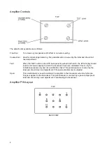
AMPLIFIER AND TRANSDUCER CONNECTIONS
Amplifier
Pin 1:
Constant current 20mA. input to amplifier.
Pin 2:
+10 volt supply.
Pin 3:
Amplifier output.
Pin 4:
Select decimal point output to ETS.
Pin 5:
0v common, (Connected to Pin F of Transducer via Transducer lead).
Pin 6:
Input from Strain Gauge Bridge, (Connected to Pin A of Transducer via Transducer lead).
Pin 7:
Select Range output to ETS.
Pin 8:
Input from Strain Gauge Bridge, (Connected to Pin B of Transducer via Transducer lead).
Pin 9:
-10 volt supply.
Pin 10:
Test switch input, Shorted to Pin 11 when Test button pressed.
Pin 11:
Supply to Bridge from amplifier, (Connected to Pin D of Transducer via Transducer lead).
Pin 12:
Supply to Bridge from amplifier, (Connected to Pin C of Transducer via Transducer lead).
Pin 13:
Not Used.
Содержание PNEUTORQUE PT 1
Страница 2: ......


