19
4.6.2
Valve Mounting
1.
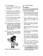
Mount the NORAC valve (
V01
) on the
sprayer using the valve mounting
bracket (
B10
).
2.
Screw short side of the threaded rods
into the bottom of the valve block at
least 3/8". The valve mounting holes are
drilled and tapped 3/8 NC-1" deep.
3.
Tighten the Hex nuts to hold the rods.
4.
Put the mounting bracket on the other
side of the tube and tighten with the
spring washers and the Hex nuts.
5.
Cut excess off of the studs, if necessary.
If using bolts, the bolts should
thread into the valve block at
least 3/8". The valve mounting
holes are drilled and tapped 3/8
NC-1" deep. The rule of thumb
for bolt length is 1-1/2" longer
than the tube size.
You must ensure no hydraulic
components will interfere with
any sprayer parts or be pulled
tight at any time.
Figure 24: Valve Mounting Location
4.6.3
Hydraulic Plumbing
WARNING!
From this point in the installation the
booms will be inoperative until the
electronics are fully installed.
1.
After the NORAC valves are mounted,
the hydraulic hoses and fittings can be
plumbed. The plumbing for the hydraulic
circuit is shown schematically in
Figure
3
.
2.
Connect a 6FJX90 hose end on the
NORAC supplied hose (
H02
) to the
Pressure port on the NORAC valve
block.
3.
Tee the “P” line to the pressure port on
the sprayer valve block using the 6FJXR-
6MJT fitting (
F04
).
4.
Connect the 6FJX90 fitting on hose
H04
to the Tank port on the NORAC
valve block.
5.
Tee in the “T” line to the tank port on
the sprayer valve block using the 8FJXR-
8MJT fitting (
F07
).
6.
The “raise” lines must be connected to
the "B" ports of the NORAC valve
block. Connect the 6FJX90 hose ends
on the NORAC supplied hoses (
H02
)
to the “B” ports of the NORAC valve
block.
7.
Tee the other ends of
H02
into the
ports of the sprayer valve block,
connecting to the boom raise cylinders
with the 6FJXR-6MJT fittings (
F04
).
The “T” fittings are inserted into
the Apache hydraulic circuit to
allow the NORAC Valve block to
control the cylinders in parallel
with the existing system.
Содержание UC4+ Apache 1010 2005+
Страница 9: ...6 Figure 3 Hydraulic Plumbing Schematic ...
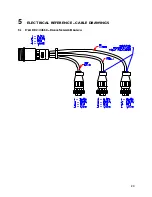
Страница 27: ...24 5 ELECTRICAL REFERENCE CABLE DRAWINGS 5 1 ITEM C02 44668 CABLE SENSOR BRANCH ...
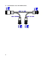
Страница 28: ...25 5 2 ITEM C02B 44664 CABLE UC4 CAN NODE DUAL ...
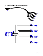
Страница 29: ...26 5 3 ITEM C03 44656D CABLE VALVE VARIABLE RATE DT ...
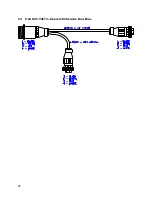
Страница 30: ...27 5 4 ITEM C05 44674 CABLE UC4 SENSOR ROLL BIAS ...
Страница 31: ...28 5 5 ITEM C10 44650 39 CABLE POWER GENERIC SELF PROPELLED L 100 2 54m ...
Страница 32: ...29 5 6 ITEM C11 44651 03 CABLE VALVE EXTENSION GENERIC 365 9 27m ...
Страница 33: ...30 5 7 ITEM C12 44658 18 CABLE UC4 VALVE AP2 MAIN ...
Страница 34: ...31 5 8 ITEM C13 44658 17 CABLE UC4 SENSE AP2 ...
Страница 35: ...32 5 9 ITEM C14 44658 99 CABLE UC4 INTERFACE POWER PIGTAIL FUSED ...

