Most of these are simply to save a few patch-cables.
The interesting one is the signals from the Sequencer, Sloth chaos and Tri
from LFO2 are mixed and fed to the S&H sample input. This means it is
continually generating stepped and smooth CVs (for there is a Slew pot) that
are different but related to everything else that is going on.
The Clock Divider gives divisions of /2, /8, /32 and /128.
The Sequencer has 4 stages but the direction control can be used to make it
count forwards and backwards enabling more complex sequences. In normal
operation, the ‘x’ output gives the CV generated by the stages 1 thru to 4,
meanwhile the ‘y’ output will give a CV signal generated by stages 4 thru to
1.
The VC Delay can be used to generate reverb type sounds but can also be pushed
into making all sorts of unexpected zipper noises and effects when the Time
and Feedback pots are turn high.
The third VCA is built into the input of the Ladder VCF. If nothing is patched
into the ‘CV VCA’ input, the VCA is always on.
The Sloth Chaos is a very slow CV generator, it can be used to liven up a
patch and create slowly evolving sounds. It cannot be controlled, it does what
it wants.
Components:
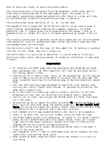
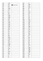
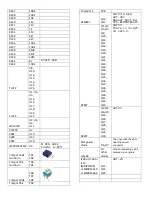
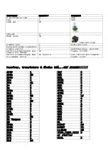
All passives are 0805; make sure the capacitors are rated for at least
25V, preferably 50V. The 10uF capacitors will only be available with a
25V rating, which is fine.
C46-C74 are all listed as 10uF, these are for decoupling. You can replace
some of them close to ICs with 100nF if you wish, but the ones near the
power connector and close to the bottom edge of the PCB should all remain
10uF.
The LFOs and Sloth have been designed to work with 2 pin bipolar LEDs.
You can just install normal LEDs instead, if you want to be boring. The
ADSR uses a regular LED.
RL in the value list means you need to choose a resistor to suit the
brightness of your LED. For blue/red 2 pin bipolar LEDs I used 5k1.
The ICs are all SOIC. You can get the PT2399 and 8 pin 78L05 from Tayda
for a few cents.
R8 and R30 can be 1k tempco thru-hole resistors OR regular 1k 0805 if you
don’t care all that much about VCO tuning stability. Do not install both
types. If you do use tempco thru-holes, install them so the resistor body
is resting on the 2 transistor pairs (Q1 & Q2, Q3 & Q4).
Part numbers are for www.taydaelectronics.com, just to give examples.
There is no R207, C73, Q25 on vers 2 PCBs, so do not look for them.
The diode numbering got a bit messed up, so ignore it. It doesn’t matter,
there are 16 LL4148 diodes and 2 S1JL power diodes, these are located
right next to the power connector, marked with a dot to indicate the
cathode and are for reverse voltage protection.
R195 (1M) can be used to reduce the maximum attack time in the ADSR. I
leave it out on my builds.
Any components with “*” next to them means they can be tweaked, for now
ignore the * and use the value given.
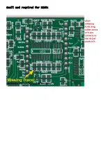
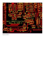
When soldering R148, drag the solder across the connect it to the via
just below
Содержание Null-A2
Страница 8: ......
Страница 9: ...Small mod required for R148 ...
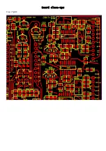
Страница 11: ...Board close ups Top right ...
Страница 12: ...Bottom right ...
Страница 13: ...Top middle ...
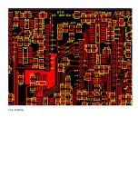
Страница 14: ...bottom middle ...
Страница 15: ...Top left ...
Страница 16: ...Bottom left ...
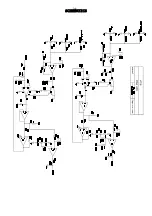
Страница 17: ...SCHEMATICS ...
Страница 18: ......
Страница 19: ......
Страница 20: ......
Страница 21: ......
Страница 22: ......
Страница 23: ......
Страница 24: ......
Страница 25: ......
Страница 26: ......


