• Tx IQ tuning and Tx power tuning can be also used in some cases.
• Remember that retuning is not a fix! Phones are tuned correctly in production.
The first set of steps instructs how to assemble the test setup. This setup is general for all Tx troubleshooting
tasks.
Alternative steps provide specific troubleshooting instructions for
Phoenix
service software.
Caution:
Never activate the GSM transmitter without a proper antenna load. There should be always
50 Ω load connected to the RF connector (antenna, RF-measurement equipment or at least 2 W
dummy load), otherwise the GSM Power amplifier may be damaged.
Steps
1. Connect a test jig to a computer with a DAU-9S cable or to a FPS-10 flash prommer with a modular cable
(XCS-4).
Make sure that you have a PKD-1 dongle connected to the computer's parallel port.
2. Connect CU-4 with 12 V supply. The DC supply voltage is set to 3.7 V by default (in Phoenix).
3. Connect an RF cable between the RF connector of the module test jig (MJ-122) and measurement
equipment or alternatively use a 50 Ω (at least 2 W) dummy load in the module test jig RF connector,
otherwise GSM may be damaged.
Note:
There are two antenna connectors in the module jig:
• one for GSM
• one for Bluetooth
Make sure that all connections are made to the correct RF connector.
Normally a spectrum analyser is used as measurement equipment.
Note:
The maximum input power of a spectrum analyser is +30 dBm.
To prevent any damage, it is recommended to use 10 dB attenuator on the spectrum analyzer input.
4. Set Tx on.
i
Set the phone module to the test jig and start
Phoenix service software
.
ii Initialize connection to the phone. (With the FPS-10 prommer use FPS10_USB or FPS10_TCP drivers,
depending on connection type. When using DAU-9S select FBUS driver).
iii From the File menu, choose product: File -> Choose Product -> xx-x* (* = type designator of the
phone, e.g. RM-237), or pressCtrl + R to scan product.
iv From the toolbar, set operating mode to “Local”.
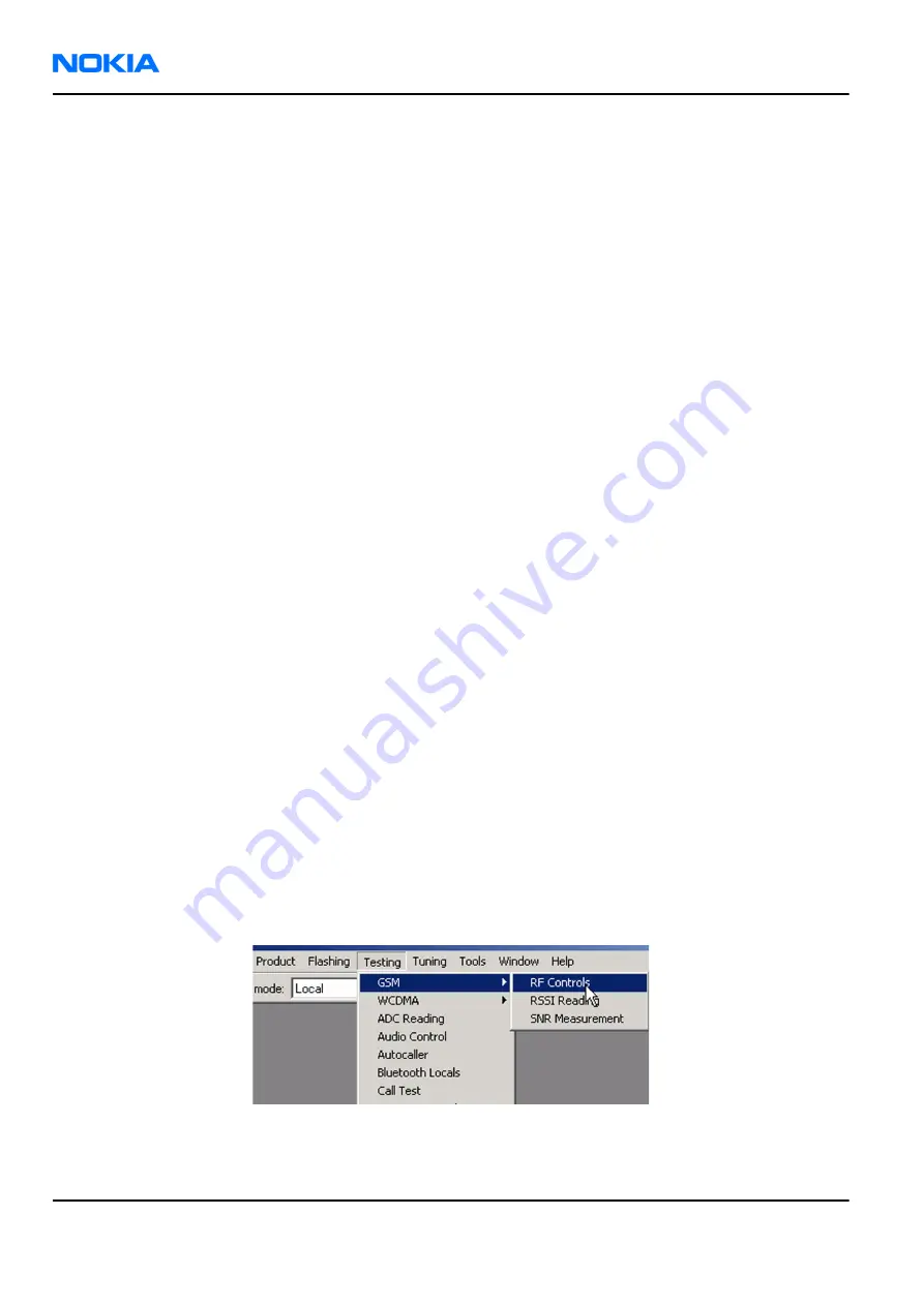
5. GSM900/1800/1900 troubleshooting
i From the Testing menu, activate the
RF Controls
window: Testing -> GSM -> RF Controls .
ii In the
RF Controls
window:
• Select band “GSM900” or “GSM1800” or “GSM1900”.
• Set Active unit to “Tx” (Default = “Rx”).
RM-237
Nokia Customer Care
RF Troubleshooting and Manual Tuning Guide
Page 7 –12
COMPANY CONFIDENTIAL
Issue 1
Copyright © 2007 Nokia. All rights reserved.
Содержание 3110c
Страница 189: ...8 System module Nokia Customer Care Issue 1 COMPANY CONFIDENTIAL Page 8 1 Copyright 2007 Nokia All rights reserved ...
Страница 207: ...9 Schematics Nokia Customer Care Issue 1 COMPANY CONFIDENTIAL Page 9 1 Copyright 2007 Nokia All rights reserved ...
Страница 218: ...RM 237 Schematics Nokia Customer Care Issue 1 COMPANY CONFIDENTIAL Page 9 12 Copyright 2007 Nokia All rights reserved ...
Страница 219: ...Glossary Nokia Customer Care Issue 1 COMPANY CONFIDENTIAL Page Glossary 1 Copyright 2007 Nokia All rights reserved ...