Noblelift PS10M Скачать руководство пользователя страница 21


20 

LED TERMINATOR DIAGRAM & DEFINITION 


FAN TERMINATOR DIAGRAM&DEFINITION 


RELAY TERMINATOR DIAGRAM & DEFINITION 


Содержание PS10M

Страница 1: ...NOBLELIFT EQUIPMENT Service Maintenance Manual PS10M Electric Pallet Truck V PS10M 01 00 Date 2013 11 20...

Страница 2: ...REPLACING OF THE CONTROL HANDLE 44 4 2 REPLACING OF THE INTERLOCK SWITCH 46 4 3 REPLACING OF THE AIR SPRING 46 5 HYDRAULIC SYSTEM 47 5 1 HYDRAULIC FLOW DIAGRAM 47 5 2 INSTALLATION OF HYDRAULIC SYSTEM...

Страница 3: ...ing must be collected and disposed of in an environment friendly way and in accordance with the directives of respective countries Such work must be carried out in areas intended for this purpose Recy...

Страница 4: ...E MANUFACTURER HAS NO DIRECT CONTROL OVER THE FIELD INSPECTION AND MAINTENANCE SAFETY IN THIS AREA RESPONSIBILITY OF THE OWNER OR OPERATOR FAILURE TO COMPLY WITH SAFETY PRECAUTIONS LlSTED IN THIS SECT...

Страница 5: ...LOTHING AND NECKTIES WHICH ARE APT TO BECOME CAUGHT ON OR ENTANGLED IN EQUIPMENT During maintenance do not allow any unauthorized person to stand near the machine Flames should never be used instead o...

Страница 6: ...ntities of water When working on the battery wear goggles or safety glasses If splashed into the eyes flush with water and get medical attention immediately Battery terminals touched by metal objects...

Страница 7: ...ul not to let any dirt or dust into the system Use only approved nonflammable cleaning solvents When changing the oil or fitter check the drained oil and filter for any signs of excessive metal partic...

Страница 8: ...6400 1195800 a 0 01 100 0 0001 1 1076 4 119 58 ft2 0 092903 0 000929 1 0 1111 144 000 yd2 0 83613 0 008361 9 1 1296 00 in2 6 4516 0 000645 0 006943 0 000771 1 1ha 100a 1mile2 259ha 2 59km2 Volume Unit...

Страница 9: ...ing charts give the standard torque specification of bolts and nuts Exceptions are given in the sections of Disassembly and Assembly METER TABLE Classification 4T 5T 10T Bolt type Bolt size Torque kgf...

Страница 10: ...1 5 41 152 2 15 2 1 1 4 74 2 7 42 208 9 20 9 1 3 4 98 8 9 88 277 8 27 8 1 1 2 128 2 12 82 360 7 36 1 The torque specifications in above table shall not be applied to the bolts with nylon packings and...

Страница 11: ...069 bar megapascal MPa 145 psi 0 00689 MPa Pa N m2 Power r W J s kilowatt kW 1 36 PS cv 0 736 kW kilowatt kW 1 34 HP 0 746 kW kilowatt kW 0 948 Btu s 1 055 kW watt W 0 74 ft lb s 1 36 W W J s Energy...

Страница 12: ...rging indicating LED 15 Drive wheel 8 Key switch 16 Chassis CONTROL HANDLE 1 Raise Lower buttons Rocker switches adjusting fork height 2 FWD BWD REV travel button Control variable speed by turning kno...

Страница 13: ...5 Extended mast height h4 mm 1970 2370 2090 2490 4 9 Height of tiller in drive position min max h14mm 934 1205 934 1205 4 15 Height lowered t h13mm 85 40 4 19 Overall length l1mm 1725 1765 4 20 Length...

Страница 14: ...13...

Страница 15: ...t Cleveland open cup O C 160 160 Pour point Max O C 35 35 Density at 15 O C kg m3 861 5 Copper corrosion 100O C 3h degree 1 1 Foaming 93 5 O C ml ml 30 0 30 0 Vickers vane pump test loss of mass on va...

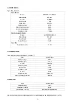
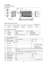
Страница 16: ...15 3 ELECTRICAL SYSTEM 3 1 ELECTRICAL DIAGRAM WIRING DIAGRAM FU1 10 A FU2 0 5 A FU01 150 A FU02 80 A...

Страница 17: ...4V Rate Power 27W Output Torque 8 N M Gear Box transmission ratio i 1 30 3 3 PUMP STATION Type MR2 B V1B F4 5 PCMAV1Y TK05C F2 Item Specification Rated voltage 24V Rated output 0 8 kw R P M 3000 rpm R...

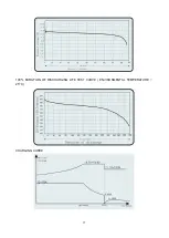
Страница 18: ...17 100 DURATION OF DISCHARGING LIFE TEST CURVE ENVIRONMENTAL TEMPERATURE 25O C CHARGING CURVE...

Страница 19: ...e 180 264 Vac 1 3 AC input voltage frequency 47 63 Hz 1 4 Inrush current 100 A 264Vac input start up in cold condition environmental temperature is 25 1 5 Max input current 3 0 A Vin 180Vac rated load...

Страница 20: ...e internal temperature drops to 60 the charger comes back to previous charge mode 3 4 Output current limiting protection 8 A CC MODE 3 5 Output short circuit protection Short circuit protection should...

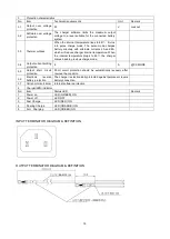
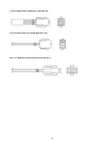
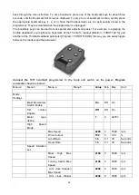
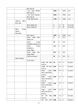
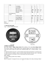
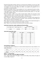
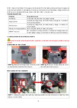
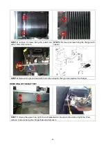
Страница 21: ...20 LED TERMINATOR DIAGRAM DEFINITION FAN TERMINATOR DIAGRAM DEFINITION RELAY TERMINATOR DIAGRAM DEFINITION...

Страница 22: ...D display rockertype keys for navigating through the display and for modifying parameters and three keys that can be used as bookmarks The 1311 programmer is easy to use with self explanatory function...

Страница 23: ...Monitor THROTTLE and another at the Throttle Deadband parameter Program THROTTLE DB this way you can easily toggle between the readout and the parameter Connect the 1311 handheld programmer to the tr...

Страница 24: ...g Left 70 0 180 Steer Angle Deadband Deg Right 110 0 180 Steer Angle Max Deg Right 180 0 180 Full Turn Speed 30 0 100 Hydro Setting Current set Lower PD Max Current 0 7 0 0 1 2 Ampere Lower PD Min Cur...

Страница 25: ...rpm Kp 20 0 100 Ki 20 5 100 Accel Rate 1 8 0 1 30 Seconds Decel Rate 1 5 0 1 30 Seconds Brake Rate 1 0 1 30 Seconds Pump Enable Off Off On 1 Speed Mode Speed Controller Max Speed 3048 100 8000 rpm Kp...

Страница 26: ...0 5 0 1 30 Seconds Pump Enable Off Off On 2 Torque Mode Speed Limiter Max Speed 4000 500 8000 rpm Kp 30 0 100 Ki 30 5 100 Kd 10 0 100 Response Accel Rate 1 0 1 30 Seconds Accel Release Rate 0 4 0 1 2...

Страница 27: ...urrent Limit 100 5 100 Regen Current Limit 100 5 100 Brake Current Limit 100 5 100 EMR Current Limit 100 5 100 Interlock Brake Current Limit 100 5 100 Power Limiting Map PL Nominal Speed 500 100 4000...

Страница 28: ...ke Brake Pedal Enable Off Off On Brake Type 5 1 5 Brake Deadband 0 5 0 5 Volt Brake Map 50 0 100 Brake Max 4 5 0 5 Volt Brake Offset 0 0 100 Brake Filter 10 2 125 Hz VCL Brake Enable Off Off On EM Bra...

Страница 29: ...5 0 200 Volt Precharge Enable On Off On Proportional Driver PD Enable Off Off On Hyd Lower Enable Off Off On PD Max Current 0 0 2 Ampere PD Min Current 0 0 2 Ampere PD Dither 0 0 100 PD Dither Period...

Страница 30: ...10 Seconds LOS Upon Encoder Fault On Off On LOS Max Speed 800 100 2000 rpm LOS Max Current 400 100 650 Ampere LOS Max Mod Depth 50 15 100 LOS Accel Rate 7 2 15 Seconds LOS Decel Rate 3 2 15 Seconds Te...

Страница 31: ...100 Inner Wheel Speed 100 10 0 0 Steer Type 5 1 5 Steer Pot Min 0 5 0 5 Volt Steer Pot Zero 2 5 0 5 Volt Steer Pot Max 4 5 0 5 Volt VCL Steer Enable Off Off On Slave Turn Accel Rate 5 0 1 30 Seconds...

Страница 32: ...lock Braking Enable On Off On Decel Rate HS 0 5 0 1 30 Seconds Decel Rate LS 0 5 0 1 30 Seconds Interlock Brake Timeout 5 0 8 Seconds CAN Interface CANopen Interlock Off Off On CAN Node ID 1 38 0 127...

Страница 33: ...Dual voltage models When vehicle voltage is the higher voltage of the 2 operating voltages Pin 8 connects to battery Pin 7 open When vehicle voltage is the lower of the 2 operating voltages Pin 7 con...

Страница 34: ...ects to a low voltage level as defined in Table 1 to activate the hour meter Leaving Pin 1 openor connecting it to high voltage gives control of the hour meter to the Hour Meter input Pin 3 Relay Pin...

Страница 35: ...h battery voltage or battery not fully charged Resets w o charging battery Not connected directly to battery terminals EMPTY too soon B connected to wrong terminal or instrument voltage does not match...

Страница 36: ...s fixing the charger with opener STEP 4 Remove the ground lead with 5mm Allen wrench then you can replace the charger REMOVING OF THE BATTERY STEP 1 Unplug the power line light line self preservation...

Страница 37: ...36 STEP 2 Press two springs of the battery cable tie loosen it STEP 3 Take out the hook STEP 4 Remove the bolts fixing pole with 10mm wrench...

Страница 38: ...n wrench STEP 2 Unplug the connector of the indicator remove 2 screws then you can remove it Instruction Blank positive pole input through the key switch positive pole output negative pole input Posit...

Страница 39: ...rshins STEP 2 Unplug the connectors fixing the cable 3 5 then you can remove the key switch REPLACING OF THE EMERGENCY BUTTON STEP 1 Remove 2 screws fixing the emergency button with wrench Avoid losin...

Страница 40: ...ncy button STEP 5 Remove B cable of the emergency button with 14mm wrench then you can remove it REPLACING OF THE FUSE ANG CONTACTOR STEP 1 Open the protective cap of the fuse holder and then you can...

Страница 41: ...Remove the fixing screws of the contactor with wrench then you can remove it REPLACING OF THE CONTROLLER STEP 1 Unplug the connectors remove screws fixing pole and 3 wiring harness U V W with 5mm All...

Страница 42: ...he controller with 5mm Allen wrench There is some thermal Silicone Grease on the back of the controller REPLACING OF THE MAGNET SWITCH STEP 1 Unplug the connectors fixing the truck body STEP 1 Remove...

Страница 43: ...Figure Application 1 Tool for removal of pins sleeves 2 Tool for application of pins sleeves 3 Tool for release of lock 4 Tool for application of secondary locking 2 pole 5 Tool for application of sec...

Страница 44: ...Bushing 23 19 17 10 8 Air spring 2 Handle mounting bracket 9 Handle cable 3 Shaft 17 10 Micro switch Z 15GW2 4 Roll pin 4x24 11 Screw M4x25 5 Socket hex bolts M8x25 12 Cover 6 Elastic washer 8 13 Scr...

Страница 45: ...or toggle button right 8 Socket hexagonal Screw M3X16 23 Tapping screw ST4 2X25 9 Washer 3 24 LED bicolor 10 Butterfly right 25 Housing for LED two parts 11 Edge Shaft 26 Spring RH throttle torsion 1...

Страница 46: ...STEP 4 Remove the driving switch axle STEP 5 Remove the screws fixing the PCB board unplug the connectors and then you can replace the PCB board Don t miss the shaft sleeve when removing the PCB boar...

Страница 47: ...Dismantle 2 screws fixing SA from the left of the handle lever with Allen wrench 4 3 REPLACING OF THE AIR SPRING STEP 1 Remove the upper screws fixing the air spring with 6mm Allen wrench STEP 2 Remo...

Страница 48: ...r but the color becames bright Fine Mixed with other oil Inspect the viscosity and if fine it can be continuously used Color changed like milk Fine Mixed with air and water Separate water or replace o...

Страница 49: ...of the pump with 24mm wrench STEP 3 Remove the cable FP fixing the contactor and cable E2 fixing the motor Then remove cable 5 4 1 J1 4 of contactor coil Watch out for the hydraulic oil spilling check...

Страница 50: ...you can replace the lowering magnetic valve 5 5 REPLACING OF THE CONTACTOR OF THE PUMP STEP 1 Remove the screw fixing the cable on the contactor with 13mm wrench STEP 2 Loosen the screw of the hoop wi...

Страница 51: ...the carbon brush will pop up by the spring 5 7 REPLACIING OF THE CYLINDER STEP 1 Remove 6 screws fixing the cover of the cylinder STEP 2 Lower the forks to the bottom remove the cotter pin of the tig...

Страница 52: ...circlip plier STEP 6 Remove the pin roll of the chain wheel STEP 7 Take out the chain wheel STEP 8 Fix the chain wheel base then remove the screws with 18mm wrench STEP 9 Take out the chain wheel bas...

Страница 53: ...2 Lift up the truck until it higher than cylinder STEP 11 Pull up the cylinder and then you can replace it 6 DRIVE WHEEL 6 1 REPLACING OF THE SENSOR Lift up the truck before operating Take care of you...

Страница 54: ...nsor and replace it 6 2 REPLACING OF THE BREAK No Part name No Part name 1 Gaiter 6 Spring 2 Friction plate 7 Carrier 3 Screw 8 Body magnetic 4 Break disk 9 Screw M5x45 5 Break anchor plate 1 STEP 1 R...

Страница 55: ...M STEP 1 Remove 2 screws fixing the cable board and 3 screws fixing the wiring harness U V W with 3mm wrench and 10mm wrench then unplug the connector STEP 2 Remove 10 screws fixing the rim with 5mm A...

Страница 56: ...antle the caster and replace it 7 2 ADJUSTING THE PRESSURE FOR THE DRIVE WHEEL After using some time the drive wheel might wear off the pressure for the drive wheel will not be enough and drive wheel...

Страница 57: ...no abnormal abrasion Check the items emphasized maintenance checklist a maintenance checklist Interval Month 1 3 6 1 Hydraulic 1 Check the hydraulic cylinder piston for damage noise and leakage 2 Che...

Страница 58: ...the main power cable for damages 32 Check the start up protection during charging Function 33 Test the audio warning signal 34 Check the air gap of the electromagnetic brake 35 Test the emergency brak...

Страница 59: ...uid type is H LP 46 DIN 51524 Viscosity is 41 4 47 Depending on the type the amount Is 3 0L Waste material like oil used batteries or other must be probably disposed and recycled according to the nati...

Страница 60: ...l quantity Truck not starts operating Battery is charging Charge the battery completely and then remove the main power plug form the electrical socket Battery not connected Connect the battery correct...

Отзывы: