Front and rear panels
18
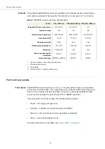
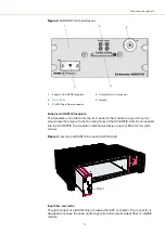
Output fiber and connector
The optical output aperture fibers and connectors are specified in
.
Handle
Grip the handle firmly, when inserting and removing the BOOSTIK from a slot in the
ACOUSTIK shelf.
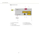
Rear panel
The BOOSTIK rear panel, shown in
, it includes the main electrical interface,
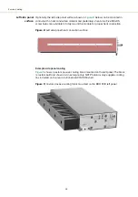
alignment holes, a heat transfer surface and three M4 tapped holes for fastening the
laser from the rear.
Figure 4
BASIK rear panel layout
Main electrical Interface
Caution:
The main electrical interface is a 30-pin male C/3 connector located on the
rear panel of the module. The interface includes pins for the following signals:
•
Serial communication – RS-485
•
Interlock – to support the
•
Emission control
•
Modulation input/output – wavelength modulation
For a complete description of the pin assignments, see
“Main electrical interface” on
Mounting screw and alignment holes
For dimensions see
1
Main electrical interface – C3
3
Alignment pin holes
2
M4 mounting screw holes
4 Heat transfer surface
2
3
1
2
4
Содержание Koheras BOOSTIK
Страница 1: ...Item 800 631 01 Koheras BOOSTIK PRODUCT GUIDE Narrow linewidth laser amplifier...
Страница 10: ...10...
Страница 14: ...14...
Страница 44: ...Module overview 44...
Страница 51: ...51 Graphing Figure 37 Graphing tab X axis setting Y axes settings...
Страница 52: ...Graphing 52...
Страница 58: ...58 2...
Страница 60: ...60 2...
Страница 66: ...66...
Страница 67: ......
Страница 68: ...1 Koheras BOOSTIK Product Description Revision 1 0 09 2021 W 10456...

