background image

Rack mounting the system

32

Rack-mounted

cooling

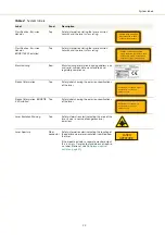
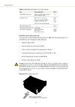
Once mounted in a rack, it is important that there is adequate airflow at the rear 
of the laser so that the cooling fins can effectively dissipate the heat generated 
by the laser – see

“Heat dissipation” on page 29

.

Forced air cooling

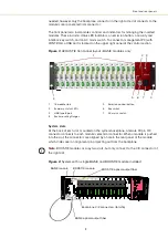
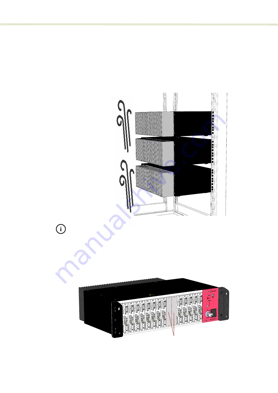
When multiple ACOUSTIK system are installed in a single rack, it is 
recommended to use forced air cooling. .

Figure 10  

Cooling a multiple system installation

Note: 

The vibration sensitivity of the installed laser modules requires rack cooling

fans installed with vibration isolation.

Blank covers

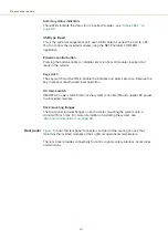
For systems that are not fully populated, place a blank cover over each 
unoccupied slot. 

Figure 11

 shows blank covers installed in slot positions 10 and 11. 

Figure 11  

Blank cover installed

Forced-air cooling
(fans) is recommended
for multiple system 
installations

Blank covers

Содержание Koheras ACOUSTIK

Страница 1: ...Item 800 633 01 Koheras ACOUSTIK PRODUCT GUIDE Multi Channel Modular Laser System...

Страница 2: ...ODUCT GUIDE This guide includes the following NKT Photonics Lasers Koheras ACOUSTIK 16 slot multi channel rack mountable modular laser system Koheras ACOUSTIK Product Guide Revision 1 0 09 2021 W 1045...

Страница 3: ...bers support product manuals Warning Use of controls or adjustments or performance of procedures other than those specified herein may result in hazardous radiation exposure BOOSTIK amplifiers If you...

Страница 4: ...es descriptions of all CONTROL menus settings and panel items Appendices The guide includes multiple appendices including laser specifications support contact details accessory descriptions and miscel...

Страница 5: ...on 17 Optical output 17 Slot configurations 18 Front and rear panels 18 Front panel 18 Rear panel 20 Modulation 22 Miscellaneous 22 Safety 22 Control 22 System and laser management 22 Status LEDs 23 S...

Страница 6: ...switch 37 LEMO connector door switch circuit 37 Bus defeater 37 Connecting power 38 Connecting modulation signals 38 Connecting the trigger input or output 38 Input trigger 39 Output trigger 39 Trigg...

Страница 7: ...to the ACOUSTIK 59 Navigation 59 ACOUSTIK modules CONTROL interface 60 Status panel ACOUSTIK system 61 Status indicators 61 System info 62 Measurements 62 WL mod button and indicator 62 Emission butto...

Страница 8: ...83 Servicing the laser 83 Support contact details 84 Support website 84 Shipping address 84 C Interface Pin Assignments 85 Modulation input output 85 External bus 85 D CONTROL Installation 87 Installi...

Страница 9: ...5 CONTROL panels and menu items 57 Table 6 Module overview fields 76 Table 7 Mechanical dimensions 81 Table 8 Operating and storage environment 81 Table 9 Electrical 81 Table 10 Safety and regulatory...

Страница 10: ...10...

Страница 11: ...h Laser SHUTDOWN 36 Figure 14 Pre wired LEMO connector 37 Figure 15 External bus defeater 38 Figure 16 Trigger input circuit 39 Figure 17 Trigger output circuit 39 Figure 18 ACOUSTIK single BASIK and...

Страница 12: ...settings 69 Figure 34 Ethernet setting 70 Figure 35 Watchdog setting 71 Figure 36 Clock setting 72 Figure 37 View setting 72 Figure 38 Menu items 73 Figure 39 Serial monitor 73 Figure 40 Serial Monito...

Страница 13: ...le 43 Procedure 3 Connecting a PC to the ACOUSTIK using Ethernet 45 Procedure 4 Enabling emission from all inserted modules 48 Procedure 5 Enabling emission from an individual BASIK module 51 Procedur...

Страница 14: ...14...

Страница 15: ...ovides a description of the laser and its system types It includes the following topics Description on page 17 Front and rear panels on page 18 Modulation on page 22 Miscellaneous on page 22 Control o...

Страница 16: ...16...

Страница 17: ...the inserted modules with a single safety interlock circuit including door and key switch control Control interfaces Serial USB or Ethernet connectivity connects a control PC to all inserted modules...

Страница 18: ...t of inserted modules is combined into a signal optical output on the rear panel of the laser As this is an advanced feature that requires a customized design contact NKTP to discuss your application...

Страница 19: ...he back of each slot mounted on the system backplane a female 30 pin C 3 connector connects to each module s electrical connector When a module is pushed into the slot the connectors are aligned by a...

Страница 20: ...e the interlock and permit emission Remove the key to prevent unauthorized laser operation AC mains switch ON OFF AC power switch that turns the system controller ON and supplies DC power to all inser...

Страница 21: ...rcuit using the supplied LEMO plug connector assembly see Connecting the safety interlock on page 35 Modulation and Trigger Male D sub 9 pin connector providing pins for wavelength input output and tr...

Страница 22: ...amplitude modulation capability contact NKT Photonics see Support contact details on page 84 Miscellaneous Safety Warning BASIK modules inserted into the system are rated as Class 3b lasers and BOOSTI...

Страница 23: ...from the OFF to the ON position Flashing Amber The system main control board is scanning for modules inserted into the system and accessories connected to the external bus ON Green Laser emission ena...

Страница 24: ...y or manufacturing information The labels are located on the panels described in Table 2 with the panels shown in Figure 6 and Figure 7 system labeling update If you inserted a 2 W BOOSTIK into an ACO...

Страница 25: ...sion specifications of the laser Laser Radiation Warning Top Safety information alert indicating this area of the laser is near a source of dangerous laser emissions Laser Aperture Fiber connector Saf...

Страница 26: ...System labels 26...

Страница 27: ...27 SECTION 2 INSTALLING AN ACOUSTIK SYSTEM This section describes how to install the laser and includes the chapters Mechanical Installation on page 29 Connecting the ACOUSTIK on page 35...

Страница 28: ...28...

Страница 29: ...posed to corrosive agents or excessive moisture heat sources or dust Operating environment Operating temperature range 15 C to 60 C Protection from dust Pollution degree 2 Office environment Operating...

Страница 30: ...ted in Table 13 on page 93 Operating the ACOUSTIK with more than two BOOSTIK modules inserted or inserting BOOSTIK modules in slots not matching the configurations in Table 13 may result in thermal da...

Страница 31: ...ack ensure to fasten the system using all four mounting holes in the system flanges two holes on each side Figure 9 ACOUSTIK installed in a 19 inch rack Caution To avoid injury and damage NKTP recomme...

Страница 32: ...d in a single rack it is recommended to use forced air cooling Figure 10 Cooling a multiple system installation Note The vibration sensitivity of the installed laser modules requires rack cooling fans...

Страница 33: ...eat generated by the modules in the system Additionally the surface should be free from vibrations and any source that could cause temperature variations Operating and storage environment Appendix A d...

Страница 34: ...Operating and storage environment 34...

Страница 35: ...ted to a switch activated by an access door to its operating area Each inserted module is connected to the system interlock circuit and when a connected door switch is opened or the circuit is shorted...

Страница 36: ...ed type Fur ther the switch must be installed in a manner so that its operation cannot be fixed in the open state using a tool Warning If the interlock is bypassed using an interlock defeater personne...

Страница 37: ...xternal bus chain When no accessory is employed the defeater is placed on the ACOUSTIK system external bus connector If no defeater is used the interlock circuit is left in the open state and disables...

Страница 38: ...ut wavelength modulation signals are described in the document Koheras BASIK Product Guide Connect modulation signals to the D sub 9 pin connector on the rear panel see Modulation input output on page...

Страница 39: ...rigger input circuit Output trigger When the trigger feature is sets the pin as an output the trigger pin should be connected to an external pull up resistor The diagram shown in Figure 16 shows a sch...

Страница 40: ...onnectors of each Koheras module ensure to check the connector tips using a fiber microscope Using the microscope check for any deformities damage residue or other contaminants at the optical tip of t...

Страница 41: ...laser and includes the chapters Mechanical Installation on page 29 Connecting the ACOUSTIK on page 35 This section describes how to manage and operate the laser and includes the chapters Communicatin...

Страница 42: ...42...

Страница 43: ...ilable in Appendix D Connecting the ACOUSTIK to a PC with CONTROL Connect the ACOUSTIK system to a PC with CONTROL installed on it using either a USB or Ethernet cable Follow the steps in Procedure 2...

Страница 44: ...n the Quick Connect panel 7 CONTROL automatically scans for any connected NKT Photonics products available on its COM ports and configured Ethernet ports 8 The CONTROL STATUS and other panels for the...

Страница 45: ...for the Ethernet connection e g ACOUSTIK 1 Host IP Addr Click on the drop down menu and select the host IP address assigned to the Ethernet port that will connect to the ACOUSTIK System IP Addr Enter...

Страница 46: ...ccess system level control and status panels Click on a module icon to access individual laser or amplifier module control and status panels Action To delete or modify a configured network port a High...

Страница 47: ...interlock and the included bus defeater installed 2 The system is connected to a PC through either a USB or Ethernet connection and the PC has CONTROL installed on it and is connected and running acc...

Страница 48: ...that are too cold or hot may lead to damage Enabling emission from all modules To enable emission from all modules inserted in an ACOUSTIK system follow the steps in Procedure 4 Note The modules are e...

Страница 49: ...on for all inserted ACOUSTIK modules click the Emission button once The emission indicator next to the Emission button is lit RED NOTE Emission is enabled for all inserted modules The Status indicator...

Страница 50: ...7 Observe status and parameters of individual modules in the Module overview panel 8 a Set the reference wavelength offset for all inserted ACOUSTIK modules using the slider in the Wavelength offset...

Страница 51: ...only NOTE Koheras BASIK controls are described in the NKTP document Koheras BASIK Product Guide 3 Ensure the front panel key switch is set to the ON position 4 Observe the Interlock indicator in the...

Страница 52: ...ndicator turns ON GREEN the module is operating normally Flashing GREEN the module has not stabilized RED a system ERROR or interlock opened with emission enabled Emission will be disabled 6 Observe t...

Страница 53: ...djust the wavelength click hold the slider to change its position b Alternatively enter the wavelength in nanometer units by typing the value into the offset input field at the upper right corner c Fo...

Страница 54: ...he following indicators Interlock GREEN Status GREEN Emission button RED 3 Select the BOOSTIK click on its icon in the Device Selector or the Module Overview panel see Module overview The control pane...

Страница 55: ...abled with no input Enable BASIK emission and re enable BOOSTIK emission to clear the error 6 a Set the emitted power level using the slider in the Power setting control To change the power click hold...

Страница 56: ...BOOSTIK module 56 7 To disable emission from the amplifier click the Emission button once The Status indicator changes to ON AMBER and the Emission button indicator turns OFF Action Status indicator O...

Страница 57: ...menus with multiple functions CONTROL menu items on page 72 Quick Connect Provides a button when clicked scans all available PC ports for connected NKTP products Connecting to the ACOUSTIK on page 59...

Страница 58: ...indow Action 1 Left click hold the top title bar of a panel 2 While holding the left mouse button down drag the panel to another position in the main window 3 When the background turns blue in a new G...

Страница 59: ...as in Figure 23 In the menu bar click the Connect drop down menu and then click on the COM port your ACOUSTIK is connected over The Control and Status panels are displayed when the system connects to...

Страница 60: ...ted the CONTROL interface only displays the selected module controls and status information ACOUSTIK modules CONTROL interface Clicking on the module icon presents the CONTROL interface for the indivi...

Страница 61: ...enu Figure 25 Status panel Status indicators The panel displays the following indicators Interlock Indicates if the door interlock and external bus interlock circuit of the system is closed or open ON...

Страница 62: ...on any inserted module System info The System Info section shows the following system serial number system firmware version Measurements Displays the system system temperature WL mod button and indica...

Страница 63: ...right corner of the Status panel Clicking the gear icon displays a menu of setting items as shown in Figure 26 Note The number of items in the settings menu may vary depending on the module types ins...

Страница 64: ...D connector Note Alternatively any inserted BASIK module can also be configured to output it s internal generator signal to the backplane signal lines Figure 27 Wavelength modulation source selection...

Страница 65: ...From the Settings drop down menu select Wavelength modulation 3 Set the source for the module to either Internal External or Both See Figure 29 Internal wavelength is modulated using the module s int...

Страница 66: ...ce for the ACOUSTIK controller to either External or Internal See Figure 30 Internal The system wavelength modulation signal lines backplane bus transmit the ACOUSTIK s internal function generator sig...

Страница 67: ...t either Sinusoidal Triangle Sawtooth or an Inverse sawtooth waveform Figure 31 Internal generator waveform selection Modulation Type Note Selecting Sawtooth sets a sawtooth modulation signal with a r...

Страница 68: ...internal modulation signal can be adjusted between 100 and 100 depending on the modulation level For example if the modulation level is set to 40 the offset can be adjusted between 60 and 60 The sum...

Страница 69: ...stem with the amplitude modulation function External amplitude modulation Inserted BASIK modules with the feature modulate their optical output power based on the signal received at the rear panel mod...

Страница 70: ...th Use this slider or text input field to set the maximum deviation in percent that the modulation signal affects the optical output power A lower value reduces the modulation achievable and vice vers...

Страница 71: ...etting The ports addresses set in ACOUSTIK and CONTROL must match MAC Address A unique MAC address of the ACOUSTIK is displayed only and cannot be set Watchdog The Koheras ACOUSTIK features a watchdog...

Страница 72: ...36 Clock setting View Check the System info and Measurements box to display the laser serial number firmware release number or system temperature within the status panel Figure 37 View setting CONTRO...

Страница 73: ...t corner X Application log In addition to the Serial Monitor the Application Log panel is used for debugging serial communications The panel displays time stamps for both COM port open and close times...

Страница 74: ...40 Serial Monitor The panel is enabled by placing a check mark on the Window pull down menu next to the Application Log item To close the panel click on the upper right corner X Clear the log Save th...

Страница 75: ...least one in serted BASIK module supports adjusting power Figure 41 Operating mode set to power Module overview When CONTROL connects to a Koheras ACOUSTIK system a Module overview panel is displayed...

Страница 76: ...vel set with CONTROL in mW Actual power mW Measured power level in mW Power setpoint dBm Power level set with CONTROL in dBm Actual Power dBm Measured power level in dBm Emission Displays status of mo...

Страница 77: ...new location to change the order of the fields in the header Togging fields on and off Right clicking on any of the fields in the header displays the menu shown in Figure 43 To remove a field from th...

Страница 78: ...Module overview 78...

Страница 79: ...clude Appendix A on page 81 Specifications Appendix B on page 83 Service and Support Appendix C on page 85 Interface Pin Assignments Appendix D on page 87 CONTROL Installation Appendix E on page 93 AC...

Страница 80: ...80...

Страница 81: ...densing All system Models Supply Voltage 100 240 VAC 50 60 Hz Maximum Power Consumption 300 W Safety Regulatory EN 60825 1 2014 Safety of laser products Part 1 Equipment classification and requirement...

Страница 82: ...82 Figure 44 Mechanical dimensions 483 00 45 00 302 50 4 50 125 00 2...

Страница 83: ...is strictly prohibited to re move any panel of the system The warranty is void if the system is opened Should the system malfunction and it cannot be serviced on site it must be shipped to the NKT Pho...

Страница 84: ...ntact NKT Photonics through our website below Support website 1 Go to https www nktphotonics com lasers fibers support technical support and customer service 2 Scroll down and click or press 3 Select...

Страница 85: ...tude Positive branch of differential input output for amplitude modulation 8 AGND 0 volt analog ground for modulation signals 10 Wavelength Positive branch of differential input output for wavelength...

Страница 86: ...n the interlock circuit is closed and has been reset This signal can be used to control safety related precautions on the External Bus 5 6 13 14 GND 0 volt ground 7 8 15 12 V 12 volt supply voltage fo...

Страница 87: ...https www nktphotonics com lasers fibers support software drivers Follow the steps in Procedure 8 Procedure 8 Installing CONTROL Action 1 On the PC launch the installer package and then click the Run...

Страница 88: ...owse button Click Next to continue 4 Uncheck the components you do not require By default all components will be installed Click Next to continue 5 Read the End User License Agreement and select I acc...

Страница 89: ...with program short cuts Use the default name or enter a new name for the folder Click Next to continue 7 Check the box to create a desktop shortcut to access Control Click Next to continue 8 Check the...

Страница 90: ...for the installation NOTE A normal install should only take a few seconds 11 Click Next to install the UART drivers for the PC USB port 12 Read the End User License Agreement and select I accept this...

Страница 91: ...s will be installed 14 The Silicon Labs drivers is installed successfully Click Finish to end the installation wizard 15 CONTROL is now installed Check the Run box to launch CONTROL when the Finish bu...

Страница 92: ...Installing CONTROL 92...

Страница 93: ...TIK Table menu B BASIK seed laser module BLC BOOSTIK Line Card laser amplifier module Table 13 ACOUSTIK slot configurations1 Config Nr of BOOSTIK Inserted ACOUSTIK system Slot 1 2 3 4 5 6 7 8 9 10 11...

Страница 94: ...LC B B B B BLC B B 33 2 B B B B B B B BLC BK BLC B B B B 34 2 B B B B B B B B BLC B BLC B B B 35 2 B B B B B BLC B B B B B BLC B B 36 2 B B B B B B BLC B B BLC B B B B 37 2 B B B B B B B BLC B B BLC B...

Страница 95: ......

Страница 96: ...1 Koheras ACOUSTIK Product Guide Revision 1 0 09 2021 W 10456...

Отзывы: