


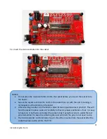

18
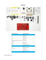
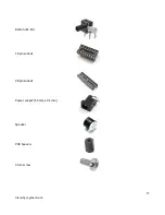
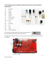
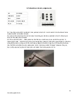
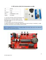
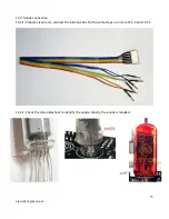
3. High voltage generator components preparation for insertion into the board and
soldering order
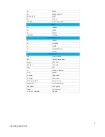
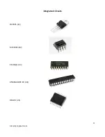
U2
MC34063
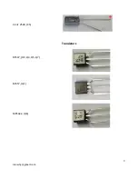
Q1
BC557
Q2
IRF840
D3
UF4004
D2
1N914
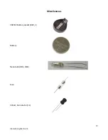
L1
Inductor 330uH
C5
2.2uF, 250V
C2, C4
0.1uF
C3
2.2nF
R4
0.5Ω 0.5W
R1
1k
R3
3.3k
R2
470k
R21
1k (Potentiometer)
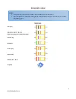
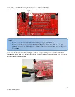
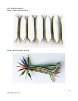
3.1. All resistors (except R4) leads bend in accordance with this picture
that each resistor place on board surface will be minimal.
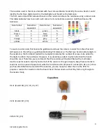
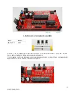
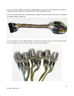
3.2. Repeat actions pointed in items 2.3, 2.3.1 and 2.3.3 for proper components insertion into the PCB
and soldering.
Содержание IN-12
Страница 9: ...9 nixiediy gmail com 2 2uF 250V C5 Transistors BC547 Q3 Q4 Q5 Q7 BC557 Q1 MPSA42 Q6...
Страница 10: ...10 nixiediy gmail com IRF840 MOSFET Q2 EL817 OK1 OK6 Diodes 1N4004 D1 UF4004 D3 1N914 D2 LED 3mm...
Страница 11: ...11 nixiediy gmail com Integrated Circuits LM7805 U1 MC34063 U2 K155 1 U3 ATMEGA328P PU U4 DS3231 U5...
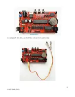
Страница 29: ...29 nixiediy gmail com An example of connecting neon bulb INS 1 is shown in the photo below...


