5
3-4. Short hose fittings
Do not fix a coupling directly on the tool. Make sure
that after a short hose is fixed with the Hose Nipple
R3/8X3/8 including in the accessories, then the
coupling be attached. If the couplings directly fixed,
it would be damaged by the vibration and the life
would be shortened.
4. PREPARATIONS
WARNING
Turn off the air supply and disconnect the air
supply hose before preparation for use.
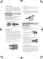
4-1. Fixing the Attachment
(Fig.2)
Fix the Hose Nipple to the Bushing (M16XRc3/8) of
the tool.
+RVH1LSSOH
%XVKLQJ0 37
Fig.2
4-2. Replacing Chisels
ACH-16 (Fig.3)
(1) For fixing the chisel, pull the Sleeve aligning the
rectangular shaped groove on the chisel with the
Throttle Lever (180°reversed side is also OK.) and
push the chisel to the end and pull it slightly till
the Sleeve returns to the External Retaining Ring.
Then, if the Sleeve does not return, leave the hand
off the Sleeve and turn the chisel left - and - right,
or move it back and - forth. When the chisel comes
to the set - position, the Sleeve automatically
returns to the External Retaining Ring.
(2) For removing the chisel, pull the Sleeve and take
out the chisel.
&KLVHO
6OHHYH
3XOOWKH6OHHYH
7KURWWOH/HYHU
5HFWDQJXODUVKDSHGJURRYH
([WHUPDO5HWDLQLQJ5LQJ
5HWXUQ
Fig.3
CH-24 (Fig.4)
(1) Rotate the Stop Ring to align the hole in the Stop
Ring with the Ball, the chisel can now be removed
or mounted.
(2) To mount the chisel, align the relief groove on the
shank with the Ball and insert the chisel until the
Ball restsin the relief groove; twist the Stop Ring
180˚ to secure the chisel.
%DOO
6WRS5LQJ
Fig.4
5. HOW TO OPERATE THE TOOL
WARNING
Do not operate tool at no load.
5-1.Start and Stop
(Fig.5)
(1) Before connecting to the air hose, make sure that
the Throttle Lever is in OFF
position.
(2) To start, hold the machine
and press the Throttle Lever.
(3) To stop, leave the hand off
the Throttle Lever.
5-2. Adjustment of Stroke
(Fig.6)
For ACH-16
Rotating the Adjust Valve
(adjusting air flow) by a flat
driver, the stroke can be
adjusted. The maximum
stroke can be obtained when
the groove on the Valve align
with the axis of the tool.
5-3. Operating Procedure
(Fig.7)
Grasp the Valve Body with one hand and place the
chisel to the work piece. Hold the Cylinder with the
other hand and press the Throttle Lever so that
the chisel starts lightly hammering the work piece.
Gradually press the lever harder to full operation
after the cutting position has been determined; this
will allow stable chipping work.
7KURWWOH/HYHU
Fig.5
$GMXVW9DOYH
0D[LPXP
0LQLPXP
Fig.6
ACH-16.indd 5
14.4.23 1:56:19 PM


