Nitgen Fingkey Access + Скачать руководство пользователя страница 1


Содержание Fingkey Access +

Страница 1: ......

Страница 2: ...ct specifications may change without prior notice to improve functionality NITGEN COMPANY the NITGEN logo are registered trademarks of NITGEN COMPANY Other names and trademarks belong to respective co...

Страница 3: ...nstallation Environment 8 Chapter 3 9 System Configuration 9 Network Mode 10 Standalone Mode 11 Chapter 4 12 Installation 12 Installation of Fixing Bracket 13 Installation of other parts 14 External C...

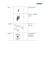
Страница 4: ...4 Chapter 1 Before Installing Product Package...

Страница 5: ...5 Product Package Item Shape Quantity Usage Terminal 1 Access controller Installation Bracket 1 Fixes the terminal Adapter 1 Supplies power to the terminal Power Cord 1...

Страница 6: ...6 Bolts 1 Fixes the terminal 3 Fixes the installation bracket Cable Door 3 Top 1ea Side 2ea S W CD 1 AccessManager Professional Software CD...

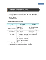
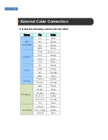
Страница 7: ...7 Chapter 2 Installation Environment...

Страница 8: ...sible due to the environment get consent from the user before installing Plug in the power only after all cables are connected While the unit is plugged in do not disconnect the cables or connect them...

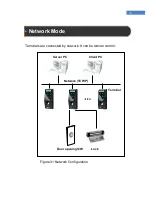
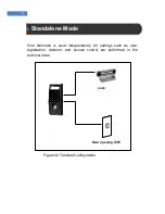
Страница 9: ...Chapter 3 System Configuration Network Mode Standalone Mode...

Страница 10: ...10 Network Mode Terminals are connected by network It can be remote control Figure3 1 Network Configuration Network TCP IP Server PC Client PC Terminal Lock Door opening S W...

Страница 11: ...ndalone Mode One terminals is used independently All settings such as user registration deletion and access control are performed in the terminal alone Figure3 2 Terminal Configuration Lock Door openi...

Страница 12: ...12 Chapter 4 Installation Installation of Fixing Bracket Terminal Connection External Cable Connection Terminal Fixing...

Страница 13: ...tall other devices such as lock and door switch Connect the external cable Fix the terminal Installation of Fixing Bracket Select a suitable installation location and fix the fixing bracket with the f...

Страница 14: ...ess than 1A Voltage output Fail Safe Secure Type Electronic Magnetic Lock Input DC12V Less than 1A Voltage output Fail Safe Secure Type Electric Strike Input DC12V Less than 1A Voltage output Fail Saf...

Страница 15: ...oller 12V Red NA Green NA White GND Black Sensor ESW Gray Not use EXIT White Door Blue Lock Brown Lock NO Green COM Yellow NC Orange GND Gray Phone Phone0 Yellow Phone1 Orange Wiegand GND Black W_IN1...

Страница 16: ...e locks do not have door monitoring signals LINE Color Function Deadbolt Strike Electronic Magnetic Lock Fail Safe Type Fail Secure Type Door Monitorin g Door Open GND Gray GND GND GND NO Open Button...

Страница 17: ...n Button Door Lock Blue Brown Door Monitoring COMMON NO Green CONTACT_B Contact COM Yellow COMMON Contact Contact NC Orange CONTACT_A Contact Normal Close N C Contact B Normal Open N O Contact A JP2 i...

Страница 18: ...18...

Страница 19: ...19...

Страница 20: ...20 4 3 2 Network Cable Connection When connecting the network cable connect to Modular Jack RJ45 Housing Cable Cabling PIN No Function RJ45 8PIN UTP 1 TXP 2 TXN 3 RXP 6 RXN...

Страница 21: ...est of the cables at the rear of the terminal and place the terminal on the fixing bracket as shown in Figure 4 2 Figure4 2 Placing the Terminal on the Fixing Bracket Fix the terminal using the fixing...

Страница 22: ...22 Chapter 5 After Installation After Installation...

Страница 23: ...below For more information see FingkeyAccess Terminal Manual and AccessManager Professional User Manual When power is supplied the initial screen with FingkeyAccess string and Time will appear Select...

Страница 24: ...on see AccessManager Professional User Manual Select the Network Normal Wireline in Admin menu of Terminal See FingkeyAccess terminal User Manual Set the network settings in the Terminal Admin menu St...

Отзывы: