background image

INSTRUCTIONS FOR USE 

146 1963 000(2)2006-06 – 

Terra™ 3700B

1

INTRODUCTION ................................................................................................................................... 2

MANUAL PURPOSE AND CONTENTS  ........................................................................................................... 2
TARGET ........................................................................................................................................................... 2
HOW TO KEEP THIS MANUAL  ....................................................................................................................... 2
IDENTIFICATION DATA ................................................................................................................................... 2
OTHER REFERENCE MANUALS .................................................................................................................... 2
SPARE PARTS AND MAINTENANCE  ............................................................................................................. 2
MODIFICATIONS AND IMPROVEMENTS ....................................................................................................... 2
SAFETY ............................................................................................................................................................ 2
SYMBOLS ......................................................................................................................................................... 3
GENERAL INSTRUCTIONS ............................................................................................................................. 3
UNPACKING ..................................................................................................................................................... 4

MACHINE DESCRIPTION ..................................................................................................................... 4

TERRA™ 3700B OPERATION ......................................................................................................................... 4
CONVENTIONS ................................................................................................................................................ 4
DESCRIPTION ................................................................................................................................................. 4

TECHNICAL DATA  ............................................................................................................................... 6

ACCESSORIES/OPTIONS ............................................................................................................................... 7

USE ........................................................................................................................................................ 7

BATTERY CHECK/SETTING ON A NEW MACHINE  ...................................................................................... 7
WET OR GEL BATTERY SETTING  ................................................................................................................. 8
BEFORE MACHINE START-UP ....................................................................................................................... 8
STARTING AND STOPPING THE MACHINE .................................................................................................. 8
MACHINE OPERATION  ................................................................................................................................... 9
HOPPER EMPTYING  ....................................................................................................................................... 9
AFTER USING THE MACHINE  ...................................................................................................................... 10
PUSHING/TOWING THE MACHINE  .............................................................................................................. 10
MACHINE LONG INACTIVITY  ....................................................................................................................... 10
FIRST PERIOD OF USE  ................................................................................................................................ 10

MAINTENANCE .................................................................................................................................. 10

SCHEDULED MAINTENANCE TABLE  .......................................................................................................... 11
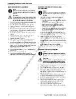
MAIN BROOM HEIGHT CHECK AND ADJUSTMENT  .................................................................................. 11
MAIN BROOM REPLACEMENT  .................................................................................................................... 12
SIDE BROOM HEIGHT CHECK AND ADJUSTMENT  ................................................................................... 12
SIDE BROOM REPLACEMENT  ..................................................................................................................... 12
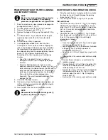
FRAME POCKET DUST FILTER CLEANING AND INTEGRITY CHECK ...................................................... 13
SKIRT HEIGHT AND OPERATION CHECK  .................................................................................................. 13
HOOD SAFETY SWITCH OPERATION CHECK  ........................................................................................... 14
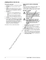
BATTERY CHARGE  ....................................................................................................................................... 14

SAFETY FUNCTIONS ......................................................................................................................... 15

EMERGENCY SWITCH .................................................................................................................................. 15
HOOD SAFETY SWITCH  ............................................................................................................................... 15
DRIVER'S SEAT MICROSWITCH .................................................................................................................. 15

TROUBLESHOOTING ........................................................................................................................ 15
SCRAPPING ........................................................................................................................................ 16

https://harrissupplyind.com - To Order Parts Call 608-268-8080

Содержание Terra 3700B 908 4203 010

Страница 1: ...S FOR USE Advance model 908 4203 010 MODE D EMPLOI ET D ENTRETIEN Mod le Advance 908 4203 010 INSTRUCCIONES DE USO Modelo Advance 908 4203 010 INSTRU ES DE USO Modelo Advance 908 4203 010 https harris...

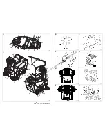
Страница 2: ...9 15 7b 7a 28 30 2 4 33 3 1 31 9 5 27 25 17 26 19 11 20 21 22 29 35 10 15 11 23 16 24 18 14 12 32 13 34 8 6 36 7 D S310027 E S310028 F S310029 G S310030 H S310198 I S310032 J S310199 K S310034 B S311...

Страница 3: ...G AND STOPPING THE MACHINE 8 MACHINE OPERATION 9 HOPPER EMPTYING 9 AFTER USING THE MACHINE 10 PUSHING TOWING THE MACHINE 10 MACHINE LONG INACTIVITY 10 FIRST PERIOD OF USE 10 MAINTENANCE 10 SCHEDULED M...

Страница 4: ...reference OTHER REFERENCE MANUALS Electronic Battery Charger Operating Manual which is to be considered an integral part of this manual Moreover the following manuals are available Spare Parts List s...

Страница 5: ...ep the battery charger cable away from heated surfaces To reduce the risk of fire electric shock or injury do not leave the machine unattended when it is plugged in To avoid electric shock do not expo...

Страница 6: ...en damaged during transportation In case of visible damages keep the packing and have it checked by the Parcel Service that delivered it Call the Parcel Service immediately to fill in a request for da...

Страница 7: ...nition switch is turned to I position optional 29 Driver s seat with safety microswitch 30 Additional hole for manual vacuum kit optional 31 Adjustable steering column 32 Working light optional 33 Sid...

Страница 8: ...SW6 Manual vacuum switch optional SW7 Working light switch General Values Machine length 49 40 in 1 255 mm Machine width w o side brooms 31 30 in 795 mm Machine height 45 47 in 1 155 mm Working width...

Страница 9: ...sories apply to an authorized retailer USE While reading this manual the operator must pay particular attention to these symbols Do not cover these plates for any reason and immediately replace them i...

Страница 10: ...the right control panel 14 Fig B Install a jumper wire 1 Fig T on the GEL connectors 3 for gel batteries Carefully reassemble the control panel 14 Fig B and fix it by using the related fixing screws...

Страница 11: ...ulky debris lift the front skirt by pressing the pedal 8 Fig C remember that while the front skirt is lifted the machine suction power decreases 3 For the machine proper operation the dust filter must...

Страница 12: ...nect the positive battery charger 7 Fig U terminal directly from the battery pole FIRST PERIOD OF USE After the first period of use first 8 hours it is necessary to carry out the following operations...

Страница 13: ...g D described in step 1 0 79 to 1 57 in 20 to 40 mm wide is 2 notches 6 Perform step 1 again to check that the main broom is at the correct height from the ground 7 When the broom is too worn and can...

Страница 14: ...ght proceeding as described in the following step 2 Unlock the ring nut 36 Fig C by turning it counterclockwise then turn the knob 33 as necessary clockwise or counterclockwise to adjust the broom hei...

Страница 15: ...Reassemble in the reverse order of disassembly SKIRT HEIGHT AND OPERATION CHECK 1 Drive the machine on a level ground that is suitable for checking the skirt height Engage the parking brake 6 and 7 F...

Страница 16: ...e vacuum fan slightly raise the hood 10 Fig C and check that the fan immediately shuts off If raising the hood 10 does not cause the vacuum fan to shut off contact an authorized Service Center or reta...

Страница 17: ...HOOTING For further information consult the Service Manual available at any Advance Service Center WARNING Check that the voltage and frequency shown on the machine serial number plate 1 Fig U corresp...

Страница 18: ...h must be disposed of properly according to the law in force Battery Polyester dust filter Main and side brooms Electrical and electronic components Plastic components and hoses Refer to the nearest N...

Страница 19: ...NEUR DECHETS 9 APRES L UTILISATION DE LA MACHINE 10 DEPLACEMENT PAR POUSSEE REMORQUAGE DE LA MACHINE 10 INACTIVITE PROLONGEE DE LA MACHINE 10 PREMIERE PERIODE D UTILISATION 10 ENTRETIEN 10 PLAN RECAPI...

Страница 20: ...e lectronique qui constitue une partie int grante de ce manuel En outre les suivants manuels sont disponibles Catalogue de pi ces de rechange livr avec la machine Manuel d entretien aupr s des Service...

Страница 21: ...ur le c ble du chargeur de batterie Tenir le c ble du chargeur de batterie loign des surfaces chaudes Pour r duire le risque d incendie choc lectrique ou blessures ne pas laisser la machine sans surve...

Страница 22: ...transport Si les dommages sont vidents garder l emballage de fa on qu il puisse tre visionn par le transporteur qui l a livr Le contacter imm diatement pour remplir une demande de dommages int r ts Co...

Страница 23: ...c microinterrupteur de s curit 30 Prise suppl mentaire pour aspirateur manuel optionnel 31 Colonne de direction inclinable en avant ou en arri re 32 Phare de travail optionnel 33 Poign e de r glage ha...

Страница 24: ...microinterrupteur brosses lat rales SW5 interrupteur de traction SW6 interrupteur aspirateur manuel optionnel SW7 interrupteur phare de travail Caract ristiques g n rales Valeurs Longueur machine 1 2...

Страница 25: ...relatives aux accessoires optionnels susmentionn s s adresser au revendeur agr UTILISATION Au moment de la lecture de ce manuel l op rateur doit comprendre le signifi de ces symboles Ne pas couvrir le...

Страница 26: ...droit 14 Fig B apr s avoir d viss les vis 13 positionner la barrette 1 Fig T sur les connecteurs 3 GEL pour batteries au gel reposer avec soin le tableau de bord 14 Fig B et le fixer au moyen des vis...

Страница 27: ...t avant en appuyant sur la p dale 8 Fig C ne pas laisser le volet avant soulev pendant une dur e prolong e pour ne pas compromettre l efficacit d aspiration de la machine 3 Pour un bon travail de bala...

Страница 28: ...t les roues ne touchent pas le sol 4 d brancher la borne positive du chargeur de batterie 7 Fig U directement du p le positif de la batterie PREMIERE PERIODE D UTILISATION Apr s la premi re p riode d...

Страница 29: ...u point 1 6 Ex cuter nouveau le point 1 pour v rifier le r glage de la hauteur de la brosse centrale du sol 7 Lorsque l usure excessive de la brosse n en permet plus le r glage remplacer la brosse com...

Страница 30: ...dant comme suit 2 D bloquer l embout 36 Fig C en le tournant dans le sens inverse aux aiguilles d une montre puis tourner la poign e 33 dans le sens des aiguilles d une montre ou dans le sens inverse...

Страница 31: ...ns l ordre inverse du d montage CONTROLE DE LA HAUTEUR ET DU FONCTIONNEMENT DES VOLETS 1 Porter la machine sur un sol plat et ad quat en tant que plan de r f rence pour le contr le de la hauteur des v...

Страница 32: ...r l g rement le coffre 10 Fig C et contr ler si le ventilateur s arr te imm diatement Au cas o en soulevant le coffre 10 Fig C le ventilateur d aspiration ne s arr terait pas s adresser imm diatement...

Страница 33: ...as le fonctionnement de la traction de la machine si l op rateur n est pas assis dans son si ge DEPISTAGE DES PANNES Pour de plus amples informations se r f rer au manuel d entretien consultable aupr...

Страница 34: ...s et les envoyer aux collectes s lectives conform ment aux normes d hygi ne de l environnement en vigueur batterie filtre poussi res en polyester brosses centrale et lat rales parties lectriques et le...

Страница 35: ...9 DESPU S DE LA UTILIZACI N DE LA M QUINA 10 DESPLAZAMIENTO DE LA M QUINA MEDIANTE EMPUJE REMOLQUE 10 PERIODO DE LARGA INACTIVIDAD DE LA M QUINA 10 PRIMER PERIODO DE UTILIZACI N 10 MANTENIMIENTO 10 E...

Страница 36: ...ter a electr nico de considerarse parte integrante de este manual Los siguientes Manuales son tambi n disponibles Cat logo piezas de repuestos en dotaci n a la m quina Manual de taller disponible cerc...

Страница 37: ...o atropellar el cable del cargador de bater as con la m quina Tener el cable del cargador de bater as lejos de superficies calientes Para reducir el riesgo de incendio electrochoque o lesiones no deja...

Страница 38: ...imiento primero quitar las bater as DESEMBALAJE Al momento de la entrega controlar con cuidado el embalaje y la m quina por si hayan sufrido da os durante el transporte Si los da os son evidentes cons...

Страница 39: ...va siempre en funci n con el conmutador de arranque en posici n I opcional 29 Asiento del conductor con microinterruptor de seguridad 30 Toma suplementaria para aspirador manual opcional 31 Columna de...

Страница 40: ...rales SW5 interruptor de tracci n SW6 interruptor aspirador manual opcional SW7 interruptor luz de trabajo Generales Valores Largura de la m quina 1 255 mm 49 40 in Anchura m quina sin cepillos latera...

Страница 41: ...les de diferentes materiales Para informaciones suplementarias sobre accesorios opcionales acudir al revendedor autorizado USO Con la lectura de este manual el operador tiene que aprender el sentido d...

Страница 42: ...ado los tornillos 13 Poner un conector puente 1 Fig T en los conectores GEL 3 para bater as de gel Remontar cuidadosamente el tablero de control 14 Fig B y fijarlo con los tornillos Volver a conectar...

Страница 43: ...pisando el pedal 8 Fig C tener en cuenta que por todo el tiempo de subida de la puerta abatible delantera la capacidad de aspiraci n de la m quina disminuye 3 Para que la m quina funcione correctament...

Страница 44: ...as abatibles el cepillo principal y las ruedas no toquen el suelo 4 Desconectar el terminal positivo del cargador de bater a 7 Fig U del polo de las bater as PRIMER PERIODO DE UTILIZACI N Despu s del...

Страница 45: ...ado en el paso 1 6 Llevar a cabo de nuevo el paso 1 para controlar que la altura del cepillo principal sea correctamente ajustada 7 Si el cepillo est demasiado consumado no se puede ajustar m s sustit...

Страница 46: ...indicaciones del paso siguiente 2 Desbloquear la virola 36 Fig C gir ndola en sentido antihorario y girar la empu adura 33 seg n necesidad en sentido horario o antihorario para ajustar la altura de lo...

Страница 47: ...LAS PUERTAS ABATIBLES 1 Llevar la m quina sobre un suelo llano y adecuado para controlar que la altura de las puertas abatibles sea correcta Activar el freno de estacionamiento 6 y 7 Fig C 2 Poner el...

Страница 48: ...TROL DEL FUNCIONAMIENTO DEL INTERRUPTOR DE SEGURIDAD APERTURA CAP Con el ventilador de aspiraci n activado abrir un poco el cap 10 Fig C y controlar que el ventilador se pare de inmediato Si la m quin...

Страница 49: ...ado en el asiento mismo B SQUEDA AVER AS Para informaciones suplementarias consulte el Manual de taller cerca de los Centros de asistencia Advance ATENCI N Controlar que la tensi n y la frecuencia ind...

Страница 50: ...eliminarlos seg n las actuales normas de higiene ambiental bater a filtros de polvos de poli ster cepillos principal y laterales componentes el ctricos y electr nicos tuber as y componentes de pl stic...

Страница 51: ...P S O USO DA M QUINA 10 EMPURRANDO REBOCANDO A M QUINA 10 DESATIVA O PROLONGADA DA M QUINA 10 PER ODO INICIAL DE USO 10 MANUTEN O 10 TABELA DE MANUTEN O PROGRAMADA 11 VERIFICA O E REGULA O DA ALTURA D...

Страница 52: ...rio do carregador eletr nico de bateria que deve ser considerado parte integrante deste manual Al m disso encontram se dispon veis os seguintes manuais Cat logo de pe as de reposi o fornecido com a m...

Страница 53: ...cabo de alimenta o seja preso numa porta nem o puxe em superf cie ou ngulos afiados N o passe com a m quina por cima do cabo do carregador de baterias Mantenha o cabo do carregador de baterias afasta...

Страница 54: ...ente as baterias DESEMBALAGEM No momento da entrega da m quina verifique com aten o se a embalagem no caso de a ter e a m quina n o foram danificadas durante o transporte Se os danos forem evidentes c...

Страница 55: ...erruptor de igni o est na posi o I opcional 29 Banco do operador com microinterruptor de seguran a 30 Tomada suplementar para kit de aspira o manual opcional 31 Coluna do volante regul vel 32 Luz de t...

Страница 56: ...nte atr s SW4 Microinterruptor das vassouras laterais SW5 Interruptor de tra o SW6 Interruptor do aspirador manual opcional SW7 Interruptor da luz de trabalho Gerais Valores Comprimento da m quina 1 2...

Страница 57: ...tativa Flaps de materiais diversos Para mais informa es sobre os acess rios opcionais acima indicados consulte um revendedor autorizado USO Ao ler o manual o operador deve dar particular aten o a esse...

Страница 58: ...arafusos 13 Instale um fio de liga o direta 1 fig T nos conectores GEL 3 para baterias ao gel Volte a montar com cuidado o painel de controle 14 fig B e fixe o com os respectivos parafusos Volte a lig...

Страница 59: ...ue enquanto o flap dianteiro estiver erguido a capacidade de aspira o da m quina diminui 3 Para um bom trabalho de varredura necess rio que o filtro de poeiras esteja o mais limpo poss vel Para manter...

Страница 60: ...o ch o 4 Desconecte o terminal positivo do carregador da bateria 7 fig U do p lo da bateria PER ODO INICIAL DE USO Ap s o primeiro per odo de uso primeiras 8 horas necess rio 1 Verificar se as pe as d...

Страница 61: ...a correta regula o da altura do solo da vassoura central 7 Quando a vassoura estiver muito usada e j n o for poss vel a sua regula o substitua a seguindo as instru es do par grafo seguinte Opera o de...

Страница 62: ...ie o anel 36 Fig C rodando o no sentido contr rio aos ponteiros do rel gio depois rode o man pulo 33 quanto for necess rio no sentido contr rio aos ponteiros do rel gio para regular a altura das vasso...

Страница 63: ...substitui o 10 Remonte as partes retiradas na ordem inversa da desmontagem VERIFICA O DA ALTURA E DO FUNCIONAMENTO DOS FLAPS 1 Coloque a m quina num terreno plano e adequado a servir como plano de re...

Страница 64: ...ente o capot 10 fig C e verifique se a ventoinha p ra de imediato Se ao erguer o capot 10 a ventoinha de aspira o n o se desligar contate um Centro de Atendimento autorizado ou um revendedor CARGA DE...

Страница 65: ...nto do sistema de tra o da m quina se o operador n o estiver sentado no banco LOCALIZA O DE DEFEITOS Para mais informa es consulte o Manual de manuten o que est dispon vel em qualquer Centro de Atendi...

Страница 66: ...e envi los s recolhas diferenciadas em conformidade com a norma ambiental em vigor bateria filtro para poeiras em poli ster vassouras central e laterais componentes el ctricos e electr nicos tubos e p...

Страница 67: ...1 3 3 2 4 6V 6V 6V 6V 12V 12V 7 7 6 20 6 4 2 3 1 6 4 5 11 10 9 19 18 16 17 15 14 12 8 13 7 L S310200 M S310036 N S310037 O S310083 P S310084 Q S310085 R S310040 S S310041 T S310201 U S311284 https ha...

Страница 68: ...RD BU RD RD VT BN RD RD RD 4 6 5 1 3 2 BK WH BK YE WH RD RD BK BU RD BU OG BK RD 30 87 J1 J2 SW4 RD WH If the ma chine have not the op tional char ger CH instal led C2 con nect ors are con nect ed t...

Отзывы: