Control System
29
Service Manual – SC2000
Machine Settings Screen (Continues)
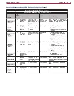
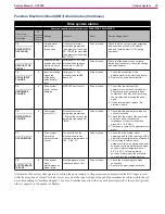
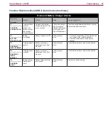
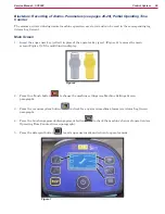
The following parameters are displayed only when, on reaching the last RESET parameter, the One-Touch
button
is pressed together with the detergent percentage adjustment button
and the detergent
flow rate adjustment button
.
If the One-Touch button
is not pressed, the system will return to the first parameter CHM1.
HIDDEN PARAMETERS
Code
Description
Min.
Value
Factory
Setting
Max.
Value
Meaning
TSERV
Service advisory timer (hours)
0
0
1000
Set to a value X greater than 0 if you wish the “Service
Advisory” icon to be displayed every X hours of
machine running time (according to the main operating
time counter). To reset the time counter for the icon
display countdown (until the next service advisory),
press the BURST and vacuum buttons for 10 seconds
with the display on the “SERVICE MENU” page.
AR
Maximum acceleration ramp
(sec.)
0.5
1.5
5
Increase to obtain a less abrupt response when
accelerating, and vice versa.
DR
Maximum deceleration ramp
(sec.)
0.5
1.5
8
Increase to obtain a less abrupt response when
decelerating, and vice versa.
WARNING: increasing this value increases the
braking distance.
IR
Maximum deceleration ramp in
reverse (sec.)
0.5
0.5
5
This is the maximum current which can be supplied to
the disc brush deck.
WARNING: increasing this value increases the risk
of motor overheating.
AMAX
Maximum lateral acceleration
(g/100)
1
15
100
It is the maximum lateral acceleration allowed to the
machine. With this value, the drive system reduces the
power to the driving wheel to keep the stability of the
machine.
WARNING: increasing this value increases the risk
of machine overturning.
KG
Lateral acceleration control
constant
1.0
1.6
2.0
Engineering parameter connected to AMAX.
- Do not change.
VS1
Brush 1 motor protection
threshold (A)
20
30
50
This is the maximum current which can be supplied to
the disc brush deck.
WARNING: increasing this value increases the risk
of motor overheating.
VS2
Brush 2 motor protection
threshold (A)
20
40
50
This is the maximum current which can be supplied to
the cylindrical brush deck (not used).
WARNING: increasing this value increases the risk
of motor overheating.
DEADL
Drive pedal bottom dead area (V)
0.0
0.9
1.5
Pedal output voltage when the pedal is released.
DEADH
Drive pedal top dead area (V)
0.0
2.2
2.5
Pedal output voltage when the pedal is fully pressed.
INOM
Drive system rated current (A)
10
15
15
This is the maximum continuous current which can be
supplied to the driving wheel unit.
WARNING: increasing this value increases the risk
of motor overheating.
IMAX
Drive system maximum current
(A)
10
45
45
This is the maximum instantaneous current which can
be supplied to the driving wheel unit.
WARNING: increasing this value increases the risk
of motor overheating.
TMAX
Protection trip time for IMAX
(sec.)
0
12
60
This is the reaction time of the driving wheel unit
protection device when overloaded: this parameter
is used in conjunction with IMAX to obtain the most
appropriate response curve for the overload protection
motor actuation system.
WARNING: increasing this value increases the risk
of motor overheating.

