background image

Содержание COOLSCAN LS-10

Страница 1: ...z I I f z Nikon Coolscan Installation Guide for Windows ikon ELECTRONIC IMAGING ...

Страница 2: ...I I I I I I I Coolscan Installation Guide I for the Windows Operating System I I I I I I I ...

Страница 3: ...This scanner has been approved by the Underwriters Laboratories Inc in the U S the Canadian Standards Association and as a class B device under Part 15 of the FCC Federal Communications Commission Rules This unit should only be installed in equipment that has been approved according to the same standards AC Line Cord Note that different power cords are needed for different line voltage If the line...

Страница 4: ...n such rerminarion Q desrroy rhe program rogerher wirh all copies modificarions and merged ponions in any form DISCLAIMER OF WARRANlY AND LIMITED WARRANlY THE SOFTWARE PROGRAM IS PROVIDED AS IS WITHOUT WARRANlY OF ANY KIND THE ENTIRE RISK AS TO THE QUALITY AND PERFORMANCE OF THE PROGRAM IS WITH YOU SHOULD THE PROGRAM PROVE DEFECTIVE YOU AND NOT TRANTOR ASSUME THE ENTIRE COST OF ALL NECESSARY SERVI...

Страница 5: ...age without prior written consent The slide is 1993 John Harcourt Page IV Trademark Information Coolscan is a trademark of Nikon Inc Nikon LS_lOTM and Nikon LS lOPMare trademarks ofNikon Corporation ImageAccesl is a trademark ofAXS Optical Technology Resource Inc Macintosh is a trademark ofApple Computer Inc WindowsTM is a trademark of Microsoft Corporation Photoshop is a trademark ofAdobe Systems...

Страница 6: ... Safery Precautions When Connecting AC Power to the LS l OE 11 I I AC Power Safery Precautions LS lOE 11 General Safery Precautions 12 Installation Precautions 13 3 The SCSI Interface 15 System Requirements for SCSI Installation 15 I Setting the SCSI ID 15 Determining Which SCSI ID Number to Use 16 Setting the SCSI ID LS l OE 17 Setting the SCSI ID LS l0 17 I Terminating the SCSI Chain 18 Terminat...

Страница 7: ... the Guide Rails 40 Before Inserting Coolscan into the Drive Bay 43 Procedure 4 2 Installing Coolscan into the Drive Bay 43 I 5 Software Installation 47 Nikon Scanner Plug in Software 47 Coolscan Control Software 47 I Eject EXE Software 47 Nikon Installer Software 48 System Requirements 48 I The Distribution Diskette 48 Running the Nikon Installer 48 The Software Installer Dialog 50 I The Product ...

Страница 8: ...0 Internal model which is mounted into your computer just like a floppy disk drive The other is the IS JOE External model which is a peripheral device and cannot be mounted into your comput er As you follow the installation procedures in this guide refer only to the sections which are appropriate to the Coolscan model you have purchased In this guide the Coolscan internalmodel will always be refer...

Страница 9: ... mount the scanner into the computer Chapter Five Software Installation Provides procedures for installing the scanner sofrware Included are the steps necessary to copy the sofrware from the distrib ution diskette provided onto the hard drive Troubleshooting Solutions to problems you may encounter in installing your Coolscan Unpacking Again ifyou have not done so already please review the Open Me ...

Страница 10: ... place Always work with the backup copies when installing the Nikon software Minimum PC System Requirements As an absolute minimum your PC or compatible computer system must be con figured with the following components Microsoft Windows version 3 0 or later version 3 1 recommended 8 Megabytes of RAM 16 32 recommended for best performance 80 Megabyte Hard Disk 300MB or more recommended I Sufficient...

Страница 11: ...monitor setting has no effect on the actual quality of your image which is always captured in 24 bit mode 16 7 million col I ors Color images occupy large amounts of disk space So make sure your hard disk has I sufficient free space to store the images you plan to scan You should have at least 60 megabytes of free space available ifyou plan on maximum resolution scans I I I I I I I I I I Nlkon Coo...

Страница 12: ... busy error indicator light Focus Wheel Power 8usy E Indicator LED rror Film Slot Insert Slide Here Nlkon IUCOOLSCAnUI Figure 2 1 Coolscan s from panel Film Slot The film slot is the opening into which you insert your slides or film strips using the enclosed film strip holder for scanning Slides and film strips are likewise ejected from the film slot A high degree of care must be exercised with th...

Страница 13: ...stays on constantly indicating that Coolscan is ready to scan Third during scanning the light will blink at two second intervals indicating that the scanning opera tion is in progress Lastly the light will blink rapidly ifan error is detected in which I case the scanner will either recover on its own or may have ro be powered off and back on ro effect a reset To summarize I Power up LED blinks at ...

Страница 14: ... next chapter The SCSI Interface Please proceed to the section Orientation and Placement of the LS IOE The Rear Panel LS l 0 The rear panel of the LS IO is shown in Figure 2 3 Note that there are three items of interest on the rear panel These are the DCpower connector SCSI connector and configuration DIP switch ector ion DIP SCSI Pin I SCSI Conn Configurat Switch External C Power Con onnector nec...

Страница 15: ...l 0 are identical Note the set of two tapped holes on each side called mounting holes as shown in Figure 2 4 One set of mounting holes on each side of the scanner will be used for the internal guide rails This procedure will be explained in detail in Chapter 4 Mounting Holes Guide Rail Locking Tab JI LS PF anel II J Tapped Holes _____ tL Figure 2 4 LS J 0 side view with guide rails Please proceed ...

Страница 16: ... Place the scanner so that it is easy to reach 3 Coolscan should be placed on a flat stable surface free from vibration 4 Keep the scanner away from damaging liquids by locating it away from sinks cof fee pots etc 5 Protect Coolscan from dampness high humidity and excessive dust or smoke Dust and smoke in particular can cause undesirable effects on the scanner s optical systems requiring extensive...

Страница 17: ... appropriate packaging materials for precision instruments Ifyou are shipping your Coolscan back to Nikon Nikon will not be responsible for damages incurred due to improper packag ing 3 The focus wheel must be turned all the way downward to the end of its travel before shipping 4 Pay special attention to the air or courier service to ensure that they can properly handle this precision instrument I...

Страница 18: ...at least 18 gauge remember the smaller the gauge the thicker the wire For example 18 gauge is thicker than 20 gauge The cord must be approved by the safety regulations of the country where it is used A properly grounded three conductor AC power source is required in order to reduce electrical noise and the possibility of electrical shock AC Power Safety Precautions LS l OE The following safety gui...

Страница 19: ...DE only 5 The housing is opened LS IDE only 6 You suspect the scanner is not functioning properly 7 Ifsomething unusual occurs such as abnormal noise odor or smoke In this case bring your Coolscan to the dealer where it was purchased or to an authorized Nikon repair facility 8 Do not attempt to insert slide mounts into Coolscan that are over 3mm thick Remount the film into an appropriate holder 9 ...

Страница 20: ... AC power switch since it relies on the PC s power Therefore make sure that the PC s power is off 2 Turn off the power to all peripherals connected to the computer display printer etc 3 Ifyour PC has a key lock facility turn the key to the unlock position 4 Unplug the AC power cable to the Pc 5 When mounting Coolscan into the PC L5 10 only be especially mindful to eliminate electrostatic discharge...

Страница 21: ...Setting Up Cooiscan Chapter 2 Page 14 Nlkon Coolscan Installation Guidefor Windows I I I I I I I I I I I I I I I ...

Страница 22: ...SI bus cabling must be correct if more than one device shares the bus 5 The SCSI bus must be properly terminated 6 Appropriate SCSI driver software must be used These requirements will be addressed in the following sections Setting the SCSI ID The SCSI bus is a sort of data highway with the SCSI devices connected to the SCSI bus representing stops on this highway Each device requires its own disti...

Страница 23: ...umber of the devices look at the rear of each for some indication If there is no indication as to the SCSI ID number then consult with the device s users manual or contact the device s manufacturer to ascertain this information Never change the SCSI ID number of a SCSI device while its power or the computer s power is on SCSIID o 2 3 4 5 6 7 Device Type Internal Disk Drive Coolscan Scanner default...

Страница 24: ...essary the SCSI 10 number of the LS lO can be set via the block of config uration DIP switches on the back of the scanner as shown in Figure 3 2 For most installations these configuration DIP switches will not require changing Configuration DIP Switch Typically reserved for computer o 4 OFF Factory default ON for Coolscan 3 OFF ON Figure 3 2 Configuration DIP switch block on the rear of Coolscan L...

Страница 25: ...ise a terminator is placed on each end of the SCSI bus T he effects of this termination may be unseen to you but are critical nonetheless Incorrect SCSI termination can cause unpredictable errors Typically the PC sits at one end of the SCSI bus Assuming this is the case the SCSI controller card in the PC must be terminated If one other SCSI device shares this SCSI bus it also must be terminated If...

Страница 26: ... a SCSI to SCSI jumper cable SCSI Terminator Figure 3 3 Artaching the SCSI terminatOr on the rear of Coolscan LS IOE Please proceed to the section SCSI Cables Terminating the LS l0 Setting termination on the LS 1 0 is simple Termination is controlled by the position of the 4 switch of the configuration DIP switch block If you recall setting the SCSI 10 number required use of only the 1 2 and 3 swi...

Страница 27: ...d with your Coolscan Externalmodel has one of each type connector on opposite ends as shown in Figure 3 5a This cable is used for the default configura tion of Coolscan which is making the scanner the last device on the SCSI bus 50 pin Centronics 25 pin OB25 F a 25 pin OB25 to c J i 50 pin Centronics SCSI Cable 50 pin Centronics b 50 pin Cen _tr _ o_ ni_ cs ______ yi to 50 pin Centronics SCSI Cabl...

Страница 28: ...ble to the existing SCSI bus in the PC connecting the SCSI cable to the PC s SCSI bus will be explained in the next section then connect the opposite end to the SCSI connector on the rear of Coolscan refer to Figure 2 3 to locate the SCSI connec tor The center connector is not used Make sure that DIP switch 4 is in the termina tion ON position as indicated in Figure 3 4 If Coolscan is to be connec...

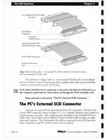
Страница 29: ...ld never be connected or disconnected while the SCSI device or the computer is powered on Such action can damage the SCSI controller card Please proceed to the section The PC s Internal SCSI Connector The PC s External SCSI Connector There are two typical SCSI connectors found on PC computers The first is the 25 pin DB25 connector shown in Figure 3 7a It is a female connector and is similar to the...

Страница 30: ...ector you will not be able to use the SCSI cable provided with Coolscan Instead you will need a 50 pin Centronics to 50 pin Centronics SCSI cable Please pro eed to the section The SCSI Chain The PC s Internal SCSI Connector The SCSI connector for internal SCSI devices on the PC is a 50 pin flat connec tor residing on the SCSI controller card Please note that Coolscan will not operate properly unle...

Страница 31: ...t there is a wide variety of 50 pin flat SCSI connectors and SCSI cables They are all functionally the same yet vaty in some important ways 1 Some cables might not have a safety key In this case take extra precautions to ensure that the mating cables connectors are properly aligned prior to insertion 2 Some connectors may not have Pin I clearly marked on the connector 3 Some cables may have Pin 1 ...

Страница 32: ...card will be required 2 Make sure that the mating connectors are aligned properly before inserting Take extra care in this very critical step 3 Push the cable connector gendy into the mating connector Once in place push down firmly Never remove a cable from the connector by pulling on the cable Ifyou cannot remove the cable by hand use a small screwdriver to pry each of the sides out a lit de at a...

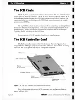
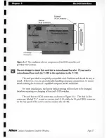
Страница 33: ...fact most devices connected to computers will be SCSI targets Typically the PC will always be the SCSI host In each case the SCSI ID number of each device must be unique The SCSI Controller Card The SCSI controller card provided with Coolscan shown in Figure 3 10 is designed for the IBM type computer standard ISA 8 bit slot This card can be config ured such that it can operate with any PC compatib...

Страница 34: ...and should be easy to install If however you are uncomfortable handling computer components we recom mend enlisting the services of a qualified computer service technician For most installations the factory default settings will not have to be changed therefore requiring no changing of the card s DIP switches The card has two SCSI connectors as shown in Figure 3 11 The dual in line connector label...

Страница 35: ...t disk operation This is not applicable with Coolscan Switch 7 and 8 should remain OFF at all times P2 controls the Zero wait state operation P3 controls the optional interrupt selection As shipped the SCSI controller card does not require any interrupt setting Ifyou have a conflict with another interface card or software you should assign an unused interrupt to the SCSI card The avail able interr...

Страница 36: ...hassis Step 3 Locate an unused expansion card slot The SCSI controller card is a half length card requiring an 8 bit ISA card slot The typical ISA computer is equipped with either 8 bit 16 bit or EISA connectors The SCSI controller card will fit into any of these connectors as shown in Figure 3 12 The card only requires a single 8 bit connector card slot Consequently it is the sim plest card to in...

Страница 37: ...SCSI connector pro truding out of the back of the computer Step 6 Tighten the ock down screw Re insert the lock down screw removed in Step 4 The hole in the metal bracket should align with the tapped hole at the back of the computer If not gently pressure the card until it does If it still does not align confirm that you have correctly inserted the card Tighten the lock down screw Care should be t...

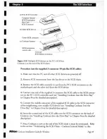
Страница 38: ... host is the PC and the SCSI target device is the scanner This simple configuration is shown in Figure 3 13 SCSI Connector a Computer SCSI Host ____ internally terminated SCSI Cable b Scanner SCSI Target I SCSI Terminator _ _ l Figure 3 13 Two SCSI devices on the SCSI bus a The PC is the SCSI host b Coolscan is the SCSI target device Procedure Use the SCSI cable supplied with Coolscan 1 Make sure ...

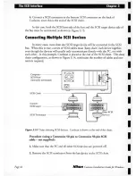
Страница 39: ...y communicate directly with the PC not with each other In this example Coolscan is placed at the end of the SCSI chain This daisy chain configuration as shown in Figure 3 14 minimizes the number of cables and con nectors required 6 Computer _ _ SCSI Host internally terminated SCSI Cable c s c l c l Scanner SCSItarget Other SCSI SCSI Terminator Devices Figure 3 14 Daisy chaining SCSI devices Coolsc...

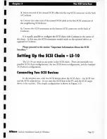
Страница 40: ...ld reside on the optional device as opposed to Coolscan Please proceed to the section Important Information About the SCSI Interface Setting Up the SCSI Chain lS l 0 The LS 1 0 can reside at any point in the SCSI chain There are essentially two possible SCSI chain configurations the two SCSI devices configuration and the multiple SCSI devices configuration Connecting Two SCSI Devices In the simple...

Страница 41: ...ble to the SCSI connector on the back I of Coolscan making sure that the connectors are properly aligned see Installing Coolscan Inco the Drive Bay in Chapter Four for detailed description In this case both the SCSI host side of the bus and the SCSI target device side of I the bus must be terminated Refer to the section Terminating the SCSI Chain LS 10 in this chapter for the proper DIP switch set...

Страница 42: ... motherboard and the other end from the SCSI device 4 Connect one end of the supplied 3 connector flat SCSI cable to the SCSI connec tor on the PC s SCSI controller card see Installing Coolscan Into the Drive Bay in Chapter Four for detailed description 5 Connect the middle connector of the supplied SCSI cable to the SCSI connector of the neighboring now middle SCSI device see Installing Coolscan ...

Страница 43: ...dized the computer to SCSI interface is not Consequently each SCSI controller may have its own comput er interface Different SCSI devices cannot necessarily be controlled with the same host code Therefore there are times when it is best to use provided SCSI controllers for different SCSI devices instead of chaining the SCSI devices 2 It is a multi device interface I I I I I I I I I As noted throug...

Страница 44: ...is managed in hard ware allowing high speed variable size block transfers In other words the SCSI inter face allows fast transfer of blocks of data Limitations The parallel bus limits the length of the SCSI chain and therefore the distance between SCSI devices 4 SCSI devices can easily be connected disconnected and moved Advantages Allows portability of devices between different computers Allows e...

Страница 45: ...The SCSI Interface Chapter 3 Nlkon Coolscan Installation Guidefor Windows I I I I I I I I I I I I I I I ...

Страница 46: ... power cable be connected to the scanner prior to mounting it into the drive bay Due to the tight space constraints inside the computer it may not be possible to connect the cables to the scanner after it is mounted The computer s power connector is typically easiest to connect when the scanner is partially inserted into the drive bay The PC s Drive Bay Your PC must have the following in order to ...

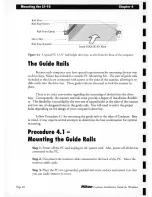
Страница 47: ...ner and rails must provide a degree of installation flexibili ty This flexibility is provided by the two sets of tapped holes in the sides of the scanner and two sets of elongated holes in the guide rails You will need to select the proper holes depending on the design ofyour computer s drive bay Follow Procedure 4 1 for mounting the guide rails to the sides of Coolscan Bear in mind it may require...

Страница 48: ...holes on the sides of the scanner called the top and bottom rail mounting holes One set ofholes must be chosen in accordance with where the computer allows the scanner to be positioned in the drive bay Most computers drive bay guide rail slots align with the scanner s lower set of mounting holes Step 8 Locate the mounting holes on the guide rails The guide rails have a tapered end and a non tapere...

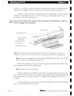
Страница 49: ... the scanner into the drive bay Check to see that its front panel is flush with the faces of adjacent devices in the drive bays and that it does not touch the other devices If these criteria are met remove the scanner and tighten down the guide rail screws Never force the scanner into the drive bay Be careful of sharp sheet metal in the drive bay while inserting and removing Coolscan If the scanne...

Страница 50: ...tructions for physically installing Coolscan Coolscan should fit snugly into the drive bay yet it should not be necessary ro apply excess force ro insert the scanner If it does not slide in easily reposi tion the guide rails or visually check the drive bay ro clear whatever might be blocking the path of the scanner The most likely source of inserrion jamming problems is the connecror cables themse...

Страница 51: ...I Aat cable to the Cooiscan SCSI connector a Rear of Coolscan Internal model b SCSI Aat cable showing keying and ribbed side facing upwards Step 3 Connect the opposite end of the 50 pin SCSI Aat ribbon cable w the 50 pin SCSI connecwr on the SCSI conrroller card Follow the guidelines in Step 2 w insert the opposite end of the SCSI cable w the SCSI connecwr on the SCSI conrroller card Step 4 Connec...

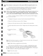
Страница 52: ...n power connector from the closest internal SCSI device 2 Plug it into the female connector of the V Adapter 3 Plug one of the male connectors of the V Adapter into the same device 4 Plug the other male connector of the V Adapter into the Coolscan power connec tor a Computer Power Connector Typical b V Adapter Power Connector Supplied ____________ Figure 4 3 Internal power connectors a Typical con...

Страница 53: ...mputer s cover making sure not to cut pinch or bendany internal cables Step 8 Reconnecr rhe monitor Step 9 Reconnect the computer s AC power cord Step 10 Start rhe Pc Start up the PC in the usual way Your disk drive should boot within a few sec onds If your PC does nor srart up as ir normally does or if Coolscan s power busy error LED indicator is not lit or continuously blinking refer to rhe Trou...

Страница 54: ...ust be used in conjunction with another software application It is called a plug in because it plugs in to a number of software applications such as Nikon ImageAccess Micrografx Picture Publisher and Adobe Photoshop PC The Nikon Scanner plug in software user interface remains the same across these and most other popular imaging applications This allows you to scan from within different application...

Страница 55: ... the SCSI driver If you are planning on using the Nikon Scanner plug in with specific third parry applications you should have all the required disks available before continuing I The Distribution Diskette The Nikon software distribution diskette contains the Coolscan Control applica I tion the ASPI driver required by the SCI controller card and the main installation pro gram called SETUP ExE The ...

Страница 56: ...Installer The Nikon Installer program is named SETUP ExE If the N ikon distribution diskette is in the A drive enter A SETUP ExE into the file name dialog then click the OK button This is illustrated in Figure 5 4 Run Dialog Click1l OK I Qommand Line Enter location and U A S Ej T U P E X E 11 I Cancel I file name of o Run Minimized I Nikon Setup rEtrowse I l Ielp Figure 5 4 Windows R UN dialog You...

Страница 57: ...er software files on the Boppy disk and copying them to a temporary file on your hard disk This will take a few moments to complete Nikon Scanner Software Setup Initializing Setup Figure 5 5 The NIKON SCANNER SOFTWARE SETUP dialog At the conclusion of the setup operation the NIKON SCANNER SOFTWARE INSTALLER dialog will appear as shown in Figure 5 6 If you want to continue with the installation cli...

Страница 58: ...IKON S CANNER S OFTWARE INSTALLER dialog The Product Selection Dialog The P RODUCT S ELECTION dialog seen in Figure 5 7 is used to indica e which Nikon produc is being ins alled The defau seieC ion is Coo scan so j US click on he CONTINUE bu on to proceed Product Selection Select the Nikon product you are installing r t I i J ijJ o LS 351OAF SCSI o LS 351OAF GPIB o LS 3500 GPIB o CP 3000D GPIB Fig...

Страница 59: ...Styler o Microgralx Picture Publisher o Adobe Photoshop Note Only the Nikon Coolscan Control is included in this package Other software must be purchased separately I inutl xit I II Help Figure 5 8 The INSTALLATION OPTIONS dialog T he default selection is Coolscan Control Ifyou select any of the other listed software products refer to the section Installi ng T hird Parry Applications in this chapt...

Страница 60: ...CSI Device Driver Options Would you like to add the Coolscan SCSI device driver to your CONFIG SYS file r p y f I p Q f Y J o Copy file but don t update CONFIG SYS o Don t copy file or update CONFIG SYS Since you are installing a SCSI scanner you must have a SCSI ASPI driver loaded A driver is supplied for the SCSI card included with the LS 10 Coolscan scanner If you choose to update the CONFIG SY...

Страница 61: ...UP Progress Indicator At the conclusion of the Coolscan Control installation you will be prompted to create a PROGRAM MANAGER GROUP FOR NIKON COOLSCAN CONTROL as seen in Figure 5 12 The Program Manager group allows you to quickly launch application soft ware by double clicking on an icon instead of typing a path in the RUN dialog in the Program Manager or having to locate the program in the Window...

Страница 62: ...sted third parry software applications in the INSTALLER O PTIONS dialog the N ikon Installer needs co know where you want the Nikon plug in software co reside T his is accomplished by entering the destination disk and path inco the PATH SELECTION FOR INSTALLER dialog shown in Figure 5 14 T he Ni kon Installer will do its best co anticipate where you want the files CO go based on your host applicat...

Страница 63: ...ler whether you will be installing new host application software and the plug in onto the destination disk or updating an already installed host application and only loading the plug in onto the des tination disk This is accomplished via the INSTALLATION M ETHOD dialog shown in Figure 5 15 If you are installing new host application software click the N EW INSTALLATION radio button then click C ONT...

Страница 64: ...the third parry vendor s installation instructions T he path of the host appli cation installation software is entered through the PATH SELECTION FOR INSTALLER dialog shown in Figure 5 14 Upon completion of the third parry application software installation you will be required to enter the destination path for the Nikon Scanner plug in This is accom plished by entering the path into the PATH SELEC...

Страница 65: ...elect the COpy FILE BUT DON T UPDATE CONFIG S yS radio burmn then click CONTINUE If you select this option you must manually enter the following line inm your CONFIG SyS fi le DEVICE D PATH MA13B SYS The last option in this dialog DON T COpy FILE OR UPDATE CONFIG SyS should only be selected when you do not wanr m complete this operation If you are attempting to use Coolscan with a third party SCSI...

Страница 66: ...e This concludes he main body of his manual The Troubleshoo ing sec ion conrains de ailed informacion on how 0 diagnose and cor recr any eype of echnical problem which may arise in conjunc ion wi h Coolscan Please proceed 0 he Coolscan User s Guidefor Windows for inS fUC ion on usage of he Coolscan scanning sofrware Nikon Cooiscan Installation Guidefor Windows Page 59 ...

Страница 67: ...Software Installation Chapter 5 Page 60 Nikon Coo scan Installation Guidefor Windows I I I I I I I I I I I I I I I ...

Страница 68: ...Installer disk Problem My system won t boot after I install the Coolscan SCSI controller card Action You have an interrupt conflict Refer ro the section on setting the SCSI card configuration which will direct you on how ro assign one of three possible inter rupts ro your SCSI host card You may have a conflict with a video card driver or a dri ver from another installed hardware device The Coolsca...

Страница 69: ...e in fact it is not For L5 10 units make certain that the SCSI ribbon cable has not been punctured or crushed when you reinstalled your PC s case Assure that the SCSI ribbon cable is firmly seated at both ends Check the position of the configuration switch for termina tion ON as indicated in Figure 3 4 in Chapter Three Problem Scanning is very slow Action Coolscan will provide the best possible pe...

Страница 70: ...canning Action Make note of the exact error message that appears then contact Nikon Technical Support It will help if you have the following file information in front of you before you call Contents of Config sys Auroexec bat Win Ini Nikon Coolscan Installation Guidefor Windows Page 63 ...

Страница 71: ...I I I I I I I I I I I I I I I ...

Страница 72: ...elvi le NY 11747 3064 516 547 4355 C 1993 Nikon Inc All brond names and product names ore the registered trademarks of their respective holders Product specifications ore subiect to change without notice EfD CfW 393 Product 29984 I I I I I I I I I I I I I I I ...
Отзывы: