background image

JAA33751-R.3646.A

- A63・AF-S VR300/2.8G -

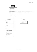
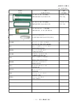
Before making the VR adjustment of defective products by using the equipment, refer to the following. 

  Criteria for VR performance

    Check

    Mount the lens on the

    appropriate body

Repeat half-pressing ON/OFF 

of the shutter release button

Set the VR mode to "ON".

Repeat pressing ON/OFF of the shutter release button a few times at 

intervals of a few seconds during half-release timer.

Judge from the controlling sound

   [Cause]


Checksum defect


Broken wire of the VCM


  (Both sides)


Mode switch defect


Others

    [Measure]

  ①

Perform the checksum with 

the equipment, then go to 
the Check 1

    ②

Confirm the breakage of the 

VCM then go to


Check 1

  ③

Make the switch


inspection with the


equipment

  ④

Go to Check 2

   [Cause]

  ①

Breakage of the VCM


(One side)

  ②

Abnormal adjustment value 

  ③

Others

   [Measure]

  ①

Confirm the breakage of


the VCM then go to


Check 1

  ②

Go to Check 2

  ③

Go to Check 2

            Go to Check 2

Do NOT control entirely

Do control only at the first stage

Do control whenever the 

half-release is ON


Go on the next page "Check 2"

How is the VR unit control?

Содержание AF-I Nikkor ED 300mm f/2.8D IF

Страница 1: ...可印 JAA33751 R 3646 A JAA33751 Copyrigh c 2005 by Nikon Corporation All Rights Reserved 無断転載を禁ず Printed in Japan January 2005 Recycled paper 再生紙を使用しています AF S VR Nikkor ED 300mm f 2 8G IF REPAIR MANUAL M サービス 計画課 ...

Страница 2: ...nal Silent Wave Motor manually via separate focus ring Vibration reduction Lens shift method using voice coil motors VCMs Shooting distance scale Graduated in meters and feel from 2 2 m 8 ft to infinity Closest focusing distance 2 3 m 7 5 ft in AF mode 2 2 m 7 2 ft in MF mode Diaphragm Fully automatic Aperture scale f 2 8 f 22 Exposure measurement Via full aperture method with cameras with CPU int...

Страница 3: ...pecial soldering iron respectively for lead free solder and lead solder They cannot be used in common Points to notice for Lead free solder products Before Disassembly Re assembly Adjustment On this lens the VR vibration reduction unit is mounted to correct the picture blur In order to maintain the functional accuracy of the picture blur correction if detaching the VR vibration reduction unit and ...

Страница 4: ... 1st lens group Detach the 1 5th lens group with a wrench J11288 Remove the retaining ring 49 with a wrench J11290 Then detach the 2nd lens group and washers 284A H 1st lens group 1st lens G rubber 1st lens group 1 5th lens group 2nd lens group 277 3 Disassembly 1 5th lens group 2nd lens group 284A H ...

Страница 5: ...JAA33751 R 3646 A D3 AF S VR300 2 8G 1st lens group 41 G1 190 3 42 G2 40 G3 4 48 43 38 89 ...

Страница 6: ...JAA33751 R 3646 A D4 AF S VR300 2 8G 297 4 Filter Filter rubber Filter Filter rubber Name plate Name plate ...

Страница 7: ... VR300 2 8G Tripod screw mount ring 204 4 182 6 135 170 206 2 139 2 116 2 186 139 2 135 B112 69 175 183A Lens body 183A D 278 Take out the screw 278 from the tripod retaining ring 175 175 Disassemble the tripod screw mount ring ...

Страница 8: ...JAA33751 R 3646 A D6 AF S VR300 2 8G External fixed tube unit 267 112 3 318 B121 Lens body 180 3 Remove the polyester tape Polyester tape This FPC will be discontinued in the middle of mass production ...

Страница 9: ...G 188 VR on off change ring Take out the lock ring connecting key 188 from the hole of the VR unit 189 2 Disassemble the VR on off change ring VR on off change ring 173 180 166 174 172 Take out 2 screws 189 from the VR on off change ring ...

Страница 10: ...3751 R 3646 A D8 AF S VR300 2 8G Fixed tube unit Fixed tube unit 105 10 98 B23 Take out 10 screws 105 from the fixed tube unit Lift fixed tube unit slowly and remove the FPC B23 from the connector Lens body ...

Страница 11: ... A D9 AF S VR300 2 8G Disassemble Fixed tube unit 114 2 B5 125 3 Fixed tube 29 133 B102 124 B103 181 83 78 103 159 39 161 178 TA 0020 B23 127 5 261 2 30 17 120 158 2 158 2 261 2 129 114 2 Solder X 2 Soldering bridge 2 ...

Страница 12: ... S VR300 2 8G Polyester tape Take out 8 screws 110 and 4 screws 106 Then remove the VR unit while being careful of each FPC 106 4 110 8 Remove the FPCs from each connector of the main PCB unit Remove the polyester tape VR unit ...

Страница 13: ...JAA33751 R 3646 A D11 AF S VR300 2 8G Aperture blade 66 3 33 B8 9 221 3 122 180 3 78 34 79 99 96 120 2 180 3 Take out 3 screws 180 to remove the aperture blade unit Tension spring 96 99 ...

Страница 14: ... VR fixing tool J11313 3rd lens group B7 Wrench J11314 NEWTOOL Fit the VR fixing tool J11313 in the VR fixed tube unit With a wrench J11314 detach the 3rd lens group B7 Remove the VR fixing tool J11313 which was fit in from the VR fixed tube unit VR unit ...

Страница 15: ... 8G Main PCB unit Take out 3 screws 111 and the washer 199 Then remove the main PCB unit B1001 and shield 280 from the VR unit 98 280 B1001 111 2 199 111 VR unit Remove the FPCs from the connectors of the VR unit Connector ー Connector ー ...

Страница 16: ...JAA33751 R 3646 A D14 AF S VR300 2 8G 369 Red Power brush unit 1 2 Remove the power brush unit 1 B96 and 2 B97 B96 97 2 97 2 B97 Black Yellow Red Black Yellow 369 Remove each wire ...

Страница 17: ...AF S VR300 2 8G Turn over the rubber ring 176 to take out the setscrew 277 176 277 Turn over SWM power FPC unit Take out the SWM power FPC unit B26 from the hole of the SWM fixed tube unit B87 B26 B87 hole B87 hole B87 hole ...

Страница 18: ...1 R 3646 A D16 AF S VR300 2 8G SWM fixed tube unit 241 12 SWM fixed tube unit B87 Change SW unit Take out 4 screws 298 While pulling the FPC remove the change SW unit B98 298 4 B98 SWM fixed tube unit B87 Hole ...

Страница 19: ...646 A D17 AF S VR300 2 8G Remove the 3 guide rollers 108 from the SWM unit 108 3 104 3 SWM unit Transparent ring unit MR ring large 277 176 167 MF ring small Transparent ring unit MF ring large 92A C n B92 B91 94 3 ...

Страница 20: ...JAA33751 R 3646 A D18 AF S VR300 2 8G SWM unit MF ring small unit Wave washer unit B34 SWM unit 62 Remove the spring B88 177A G n ...

Страница 21: ...JAA33751 R 3646 A D19 AF S VR300 2 8G MF rotation detecting brush unit White Orange 294 2 MF rotation detecting brush unit 312 ...

Страница 22: ...AF S VR300 2 8G 192 Remove the lead wire FL FPC from the relay FPC unit Remove the wave washer 192 and FPC retainer 203 from the fixed tube unit 203 Lead wire Wave washer FPC retainer AF lock ring White Brown Relay FPC unit ...

Страница 23: ...JAA33751 R 3646 A D21 AF S VR300 2 8G Detach the AF lock ring from the front fixed tube by taking out 4 setscrews 67 67 4 TA 0002 15 50 Remove the polyester film AF lock ring ...

Страница 24: ...02 Remove the tape TA 0002 5 30 from the relay FPC unit connector Relay FPC unit Connector Remove 4 AF lock rubbers 64 from the AF lock ring 52 52 64 4 Detach the AF lock FPC unit B75 from AF lock ring 52 by taking out 8 screws 114 144 8 B75 GMR unit ...

Страница 25: ...unit B70 from the connector of the fixed tube unit then remove the FPC Connector B70 Remove Remove Take out 2 screws 115 and remove the GMR unit from the fixed tube unit 115 2 GMR unit Remove GMR unit Remove the FPC of GMR unit from the relay FPC unit connector Relay FPC unit connector ...

Страница 26: ...JAA33751 R 3646 A D24 AF S VR300 2 8G Front fixed tube unit 210 2 Fixed tube unit Front fixed tube 210 2 B70 B69 109 12 Gyro unit ...

Страница 27: ...nit B69 into the front fixed tube then fix them with 4 screws 210 Front fixed tube Adhesive Lockend B 210 2 B70 B69 Insert the gyro relay FPC unit B70 into the connector of the gyro unit B69 to connect them Note Do not put the Lockend B on the screws for GND 109 12 Apply to screw threads Adhesive Lockend B Apply to screw threads Screw hole for GND Screw for GND Gyro unit 2 Assembly Adjustment ...

Страница 28: ...ess to attach with fingers Press to attach with fingers Attach the GMR unit on the fixed tube unit with the screws 115 Adhesive Lockend B 115 2 GMR unit Note Attach the GMR unit with its head touching the magnetic tape and get the GMR unit upright vertically to the tape Align the positioning holes of the fixed tube unit with the holes of the relay FPC unit connector then press to attach them with ...

Страница 29: ...power supply Set value 5 0 V 100 mA Communication tool J15416 Switch tool J15355 Connect all GND of the probe to the terminals of GND of the switch tool New tool Output waveform inspection of GMR encoder GMR unit Insert the GMR unit B19 into the relay FPC unit connector Relay FPC unit connector ...

Страница 30: ...ect Turn the switch 1 to OFF switch 2 to OFF and switch 3 to ON of the Switch tool Confirm that the electric current and voltage of the connected rated voltage power supply are set values then turn it ON Set the oscilloscope and turn the focus ring manually Check the waveform of the oscilloscope by stopping with START STOP key Note The waveform varies according to the rotational speed of the focus...

Страница 31: ...If this is not the case the GMR head may malfunction so be sure to replace the GMR holder unit and make a readjustment As shown in Fig 2 if the amplitude partially drops between the infinity and the close distance the magnetic data of the tape may be damaged In this case replace the fixed tube unit and make a readjustment Replacing only the magnetic surface is impossible Turn off the rated voltage...

Страница 32: ...he screw 5 30 TA 0002 Attach the tape TA 0002 5 30 on the relay FPC unit connector Relay FPC unit connector Assemble the 4 AF lock rubbers 64 into the AF lock ring 52 52 64 4 Attach the AF lock FPC unit B75 to the AF lock ring 52 with 8 screws 114 144 8 B75 2 Attach tape Adhesive Lockend B ...

Страница 33: ...67 4 Fold down the 3 excess parts TA 0002 15 50 Fold down the excess parts of the AF lock FPC unit at 3 locations then attach the polyester film Grease OS 30MF Grease F 890 Apply to the entire circumferential surface that contacts with the front fixed tube Apply to the entire circumferential surface of approx 5 mm in width Front fixed tube ...

Страница 34: ...e FL FPC on the relay FPC unit Assemble the FPC retainer 203 and wave washer 192 into the fixed tube unit 203 Check the height of the wave washer 192 1 8 0 1mm Wide convex portion Wide concave portion Lead wire FPC retainer Wave washer White Brown Relay FPC unit ...

Страница 35: ...WM unit 62 Check the spring hooked Assemble the focusing index ring unit B85 into the SWM unit B22 B22 Adhesive C 8008B B85 Note The assembly here is just temporary for Position adjustment of Distance encoder brush on the next page So apply the adhesive to the spring 62 at the stage of SWM unit on Page A13 Adhesive C 8008B Adhesive C 8008B ...

Страница 36: ...d align the index and the mark of the distance scale Loosen 2 screws 72 so that the distance brush B61 touches the index of the distance encoder then make an adjustment by moving the distance brush B61 After tightening 2 screws 72 fix them with Screw lock After the adjustment remove the tentative 3 screws 241 and detach the SWM fixed tube unit B87 and SWM unit 72 2 Align position Focus lead ring I...

Страница 37: ...washers 177A G n 37 179 177A G n MF ring small unit B88 After the adjustment remove the SWM fixed tube unit B87 and MF ring small unit Assemble the SWM fixed tube unit B87 MF ring small unit B88 washers 179 and 177 and check the backlash amount Grease OS 30MF Apply to the entire circumferential contact surface Grease GE 8 Apply to the entire circumferential surface that contacts with 177 Put the b...

Страница 38: ...ation detection brush unit Attach the MF rotation detection brush unit White Orange 294 2 Adhesive Screwlock MF rotation detection brush unit Attach the polyester tape 312 on the lead wire of the MF rotation detection brush unit 312 Solder wires ...

Страница 39: ...ll unit Wave washer unit SWM unit Assemble the MF ring small unit B88 wave washer unit B34 and SWM unit SWM unit 62 Check the spring hooked Check the height of the wave washer unit B34 4 0mm MF ring small unit Wave washer unit B34 Adhesive Screw lock ...

Страница 40: ...hat when the MF ring is rotated the focus lock ring subsequently turns together with it and also when the MF ring is further rotated all the way to the end the SWM unit does not turn Adjustment In case defectives are found in the above adjust by changing the washers 92A C that are put between the transparent ring unit B91 and the adjustment ring unit B92 After the inspection and adjustment remove ...

Страница 41: ...JAA33751 R 3646 A A15 AF S VR300 2 8G MF ring large unit 176 167 Grease GE 8 G92KA 4 6 MF ring large unit Apply to the entire circumferential sliding surface of the AF lock ring 52 ...

Страница 42: ... of 4 setscrews 67 so that the MF ring large operates smoothly Adhesive Screwlock 67 4 TA 0002 MF ring large Adhesive Lockend B Note Do NOT apply Lockend B to the screws for GND Screw for GND Hole for GND After adjusting the tightening of setscrews cut the polyester tape TA 0002 into appropriate size and attach it Apply to the sliding surface with the MF ring small ...

Страница 43: ...d check the smoothness of the MF ring operation by fixing the setscrew 277 176 277 Turn over SWM power FPC unit Pass the tip of the SWM power FPC unit B26 through the hole of the SWM fixed tube unit B87 and attach it B26 B87 hole B87 hole B87 hole B87 hole Reference position for attachment ...

Страница 44: ...semble the power brush unit 1 B96 and 2 B97 into the SWM fixed tube unit B87 with 2 screws 97 B96 97 2 97 2 Adhesive Screwlock Adhesive Screwlock B97 Solder the power brush unit 1 B96 2 B96 and 6 lead wires on the SWM power FPC unit B26 Black Yellow Red Black Yellow 369 ...

Страница 45: ... the main PCB unit B1001 and shield 280 on the VR unit with the washer 199 and 3 screws 111 3 98 280 B1001 111 2 199 111 VR unit Insert the FPC into the connector of the VR unit to connect them Connector Connector Adhesive Screwlock Adhesive Screwlock ...

Страница 46: ...R fixed tube unit Apply the Screwlock to the threads of the 3rd lens group B7 spreading approx 5 10 mm in length By using the wrench J11314 mount the 3rd lens group B7 on the VR fixed tube unit Remove the VR fixing tool J11313 which was fit in from the VR fixed tube unit Adhesive Screwlock Apply to the threads spreading approx 5 10 mm in length VR unit ...

Страница 47: ... 178 TA 0020 B23 127 5 261 2 30 17 120 158 2 158 2 261 2 129 114 2 Adhesive Lockend B Grease G92KA Adhesive Lockend B Adhesive Screwlock Adhesive Screwlock Adhesive Screwlock Adhesive Screwlock Soldering bridge 2 Solder Adhesive Lockend B Adhesive Lockend B Adhesive Lockend B Adhesive Lockend B Black matte paint Black matte paint ...

Страница 48: ...them temporarily with 3 screws 105 Note The FPC that connects from the rear fixed tube unit is temporarily attached without being inserted into the connector When assemble the above be careful not to pinch etc the FPC Pass the FPC through the hole of the rear fixed tub unit Hole Measure the 3 1 lever Loosen 2 screws 158 and move the 3 1 lever block 39 so that the above width becomes 3 1 0 1 0 1 Pr...

Страница 49: ...A A23 AF S VR300 2 8G Aperture blade 66 3 33 B8 9 221 3 122 180 3 78 34 79 99 96 120 2 Assemble the aperture blade unit Apply to 2 screws 120 and the screw 99 Tension spring 96 99 Adhesive Screwlock Adhesive Screwlock ...

Страница 50: ...aperture unit to adjust the aperture diameter Standard Aperture blade is positioned leaving space of 1mm 0 2mm in the largest part from the inside diameter of the aperture action plate After the adjustment apply Screwlock on 3 screws 221 Aperture blade 34 Grease I 40 24 180 3 221 3 Adhesive Screwlock 1 0 2mm Inside diameter of Aperture action plate Aperture blade January 27 2005 2 Change page Addi...

Страница 51: ...ube unit After the adjustment make a mark off line Then remove the temporarily attached 3 screws 105 and detach the VR unit from the rear fixed tube unit Note Do not put the unit with the aperture blade side down on a desk etc because it could cause a deformation of the aperture blade unit ...

Страница 52: ... SW unit B98 through the hole of the SWM fixed tube unit B87 and assemble them with 4 screws 298 298 4 B98 SWM fixed tube unit B87 Hole VR unit Pass each FPC which connects from the lens body through holes of the VR unit to assemble them VR unit Adhesive Screwlock Positioning pin ...

Страница 53: ...ge SW unit 106 4 110 8 Adhesive Lockend B Pass each FPC through the holes of the VR unit and connect them to each connector of the main PCB unit While confirming that the FPC does not become slackened attach the polyester tape TA 0001 on it Use the tape with 8 10 mm in width Adhesive Lockend B Change SW unit TA 0001 ...

Страница 54: ...line B5 B23 Connect the FPC B23 of the rear fixed tube unit to the connector of the main FPC Assemble the fixed tube unit into the body lens with 10 screws 105 Adhesive Screwlock Lens body Memory set FPC SW Check the electrical continuity of GND line between the bayonet mount and the memory set FPC SW Bayonet mount 180 Connector ...

Страница 55: ... of the VR unit 189 2 Adhesive Lockend B Assemble the VR on off change ring VR on off change ring Adhesive Lockend B 173 180 166 174 172 Fix 2 screws 189 on the VR on off change ring Grease GE 8 Apply to the entire circumferential sliding surface of the inner diameter Grease GE 8 Apply to sliding surface of 172 and 173 ...

Страница 56: ...h is surely put on the right side pattern of the PCB 111 By moving the brush for adjustments and tighten the screw 111 Brush Cut the polyester tape into appropriate size then fix it on the FPC Polyester tape This FPC will be discontinued in the middle of mass production Adhesive Screwlock Fixation of FPC Right side pattern ...

Страница 57: ...3 screws 112 and 3 screws 180 Press the knob 173 to check the rotation of the VR on off change ring 267 112 3 318 B121 Lens body 180 3 173 Grease OS 30MF Apply to the entire circumferential jointing surface Apply to the entire circumferential jointing surface Grease I 40 Apply to the contact surface with 174 at 2 locations Grease OS 30MF ...

Страница 58: ...ter Grease OS 30MF Grease EBB8041 Apply to the contact surface with 183 278 Fix the tripod retaining ring 175 with the setscrew 278 175 Grease EBB8041 Apply to the contact surface of the outer diameter at 2 locations Adhesive Lockend B Adhesive Lockend B Adhesive Lockend B Adhesive Lockend B Grease EBB8041 Apply to the screw Apply to the entire circumferential surface spreading approx 2 mm wide Gr...

Страница 59: ...JAA33751 R 3646 A A33 AF S VR300 2 8G 297 4 Filter rubber Filter Filter Filter rubber Name plate Name plate Adhesive Lockend B ...

Страница 60: ...3646 A A34 AF S VR300 2 8G 1st lens group 41 G1 190 3 42 G2 40 G3 4 48 43 38 89 Note When the vinyl electric wire 48 is replaced tighten the retaining ring 43 once then in a few minutes retighten it Grease EBB8041 ...

Страница 61: ...e way to the closest distance Put the washers 284A H and fit the 2nd lens group into the lens body Put the retaining ring 49 with a wrench J11290 and fix the 2nd lens group Fit in the 1 5 lens group with a wrench J11288 1st lens group 1st lens group rubber Adhesive EDZ4113 2nd lens group 1 5th lens group 1st lens group ...

Страница 62: ...up and washer 284 For a difference between the value and the standard value adjust the thickness by selecting the washers 284A H If the difference is positive increase the washers If it is negative decrease the washers Standard 0 0 25 mm In case it is within standard confirm the alignment by the collimator Standard Center of mark 2 3 Note If the back focus collimator J19002 is NOT available while ...

Страница 63: ...ace cannot be used As long as the above requirements are met either desktop or notebook PC is available Preparation for inspection adjustment of main PCB In case of replacing the main PCB SWM unit or MR encoder unit be sure to make the necessary adjustments as follows 1 Adjustments Adjust the MR duty Adjust the driving frequency and motor control including Focus preset adjustment 2 Equipment and t...

Страница 64: ...the personal computer is a 9 pin type connect it by using the 25 pin 9 pin conversion connector RJ does not supply this connector Use products on the market Personal computer This system does not depend on the CPU type of personal computer AF I communication adapter J15307 To RS232C terminal AF I communication box J15306 1 Oscilloscope Power supply 6V ...

Страница 65: ...ues in EEPROM appears Select the appropriate item Following the instruction on the screen rotate the MF ring slowly by hand in the direction from the infinity to the close distance position Make sure that the waveform on the oscilloscope has duty 50 and stop the MF ring at the close distance end Setting of oscilloscope V Div CH1 5V V Div CH2 5V Coupling DC Time Div 5 m Sec Trigger Mode NORMAL Trig...

Страница 66: ...ng select No to make adjustments again In case the motor does not stop driving even after the readjustments adjust the MR duty again and repeat ADJUSTMENT FOR DRIVING FREQUENCY MOTOR CONTROL If the adjustment is not successful in spite of the above the SWM unit fix tube unit or MR head unit may be defective Fig 1 Adjustment of Driving frequency and Motor control In case of replacing the main PCB S...

Страница 67: ...using the oscilloscope In case the irregularity of mechanical operations does not take place in the focus ring driving unit the servo time tends to be long if it is heavy in the cam ring rotation of the MR encoder while the servo time tends to be short if it is light in its rotation of the MR encoder 4 Switches and lenses Check the ON OFF operations of switches and the operating condition of the d...

Страница 68: ...on the focal length selection the voltage setting the inspection mode start The screens depend on the items Follow the instructions of the personal computer Operating voltage Power supply for AF motor inside lens Power supply for AF I communication box Inspection of MR encoder operation 6 0 0 1 V Inspection of lens servo stop accuracy 6 5 0 1 V 5 5 0 2 V Inspection of lens servo time 6 5 0 1 V Ins...

Страница 69: ... driven the pulse shows an abnormal value Do NOT touch the MF ring during operations Make inspections at the 5 positions as below Lens inclination Position of index window Horizontal Up right and left Front lens group 90 upward Front lens group 90 downward Lens position in inspecting When the inspection ends the result of the next page appears ...

Страница 70: ...JAA33751 R 3646 A A44 AF S VR300 2 8G The difference in pulse before and after the inspection must be within the standard Standard Total pulses 14502 150 PLUSE S ...

Страница 71: ... delay time msec millisecond which prevents stopping the lens Fig 2 3 Inspection of lens servo stop accuracy Note The value of ADUST DELAY TIME is set by the adjustment software So if the lens does not stop during the inspection of LENS DRIVING STOP ACCURACY any value can be input without problem However the larger the value of ADJUST DELAY TIME gets the longer the inspection time becomes ...

Страница 72: ...ft Front lens group 90 upward Front lens group 90 downward Lens position in inspecting The number of overrun underrun pulses must be within the standards after the 5 lens back and forth driving motions 5 5TIME S in 1 of the display Standard RATIO 1 is 40 or less for Df1 Df6 of the screen Occurrence ratio of 10 27 pulses RATIO 2 is 10 or less for Df1 Df6 of the screen Occurrence ratio of 19 27 puls...

Страница 73: ...ections the waveform shows an abnormal value Do NOT touch the MF ring during inspections Make inspections at the 5 positions as below Lens inclination Position of index window Horizontal Up right and left Front lens group 90 upward Front lens group 90 downward Lens position in inspecting E terminal H terminal E terminal H terminal Oscilloscope setting V Div 5V Coupling DC Time Div 20 m Sec Trigger...

Страница 74: ...tion of switches and lens conditions Type of lens The version of CPU in the lens The signals of the focusing encoder and zooming encoder The value changes by turning the MF ring with M or M A of the lens driving mode selector The status of Switches ...

Страница 75: ...iving frequency motor control Inspection adjustment for MR encoder operations lens servo stop accuracy lens servo time switches lens condition VR adjustment Main PCB unit SWM unit VR unit Jyro unit GMR unit Fix tube unit Necessary adjustment when replacing parts Parts to be replaced Adjustments ...

Страница 76: ...Mount the lens on the equipment Set the infinity mark of the focus ring to the index Refer to the next page for Procedure for mounting the lens WARNING This equipment uses the laser beam Do not look at the laser beam directly or through the laser beam window Notes Keep the approx 5 m distance from the laser beam window to the radiated surface Do not block the light path of the laser beam RS232C ca...

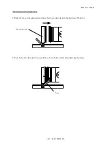
Страница 77: ...etainer stand Clamp Procedure for mounting the lens 1 Mount the lens on the equipment and move the lens retainer stand in the direction of the arrow 2 Move the lens retainer stand to the position as shown below and fix it by tightening the clamp ...

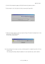
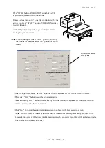
Страница 78: ... If the below message appears reset the zoom ring by referring to Procedure for mounting the lens on the previous page Then click OK button The focus ring is automatically set Note Do not change the lens settings zoom ring until the adjustment is completed and go back to the Lens selection screen If the setting position changes during the adjustment the correct adjustment value cannot be obtained ...

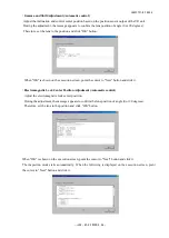
Страница 79: ... VR300 2 8G VR Mode Switch Inspection screen appears Point the cursor to the check box before VR Mode Switch Inspection and click it Point the cursor to the Execute button and click it Vibration Reduction mode switch inspection ...

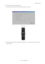
Страница 80: ...tion of VR mode switch is indicated Selecting the VR mode switch indicates the current position in the real time VR mode switch When completing the VR mode switch inspection point the cursor to Exit button and click it to exit the inspection screen ...

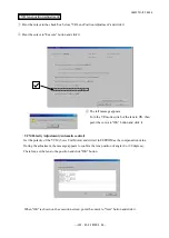
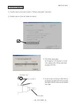
Страница 81: ...h of the lens to ON then point the cursor to OK button and click it VCM Polarity Adjustment Automatic control Get the polarity of the VCM Voice Coil Motor and write it in EEPROM as the compensation value During the adjustment the message appears to confirm the lens position of angle 0 or 90 degrees Therefore set the lens to the position and click OK button When OK is shown on the execution screen ...

Страница 82: ...the execution screen point the cursor to Next button and click it Electromagnetic Lock Center Position Adjustment Automatic control Adjust the electromagnetic lock center position During the adjustment the message appears to confirm the lens position of angle 0 or 90 degrees Therefore set the lens to the position and click OK button When OK is shown on the execution screen point the cursor to Next...

Страница 83: ... OK is shown on the execution screen point the cursor to Next button and click it When the message Finished rewriting checksum value is shown click OK button Turn the VR switch to OFF according to the message and click OK button to exit the adjustment screen Note If NG is shown during the adjustment click Next button to exit the inspection mode Go back to the Lens Selection screen after rewriting ...

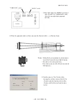
Страница 84: ...r to Execute button and click it The left message appears Set Frequency of Telephoto to 5 0 Hz in the settings of the VR lens adjustment equipment J15380 Laser pointer Laser switch knob Nut Viewed from above Loosen the laser switch nut of the VR lens adjustment equipment J15380 and rotate the knob in the arrow direction to irradiate laser light ...

Страница 85: ...rate measure the vibration width α of the laser beam Notes During the above measurement a phenomenon occurs which causes laser spot light swinging from side to side and up and down This is the movement of the VR unit control and NOT defective Point the cursor to Next button in the message box on the screen and click it The vibration reduction function starts and the vibration width of the laser be...

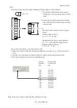
Страница 86: ...s wait for a few seconds until the vibration movement stabilizes Buttons for adjusting Gyrog Gain Buttons for adjusting Angle misalignment Gyro Gain Adjustment Adjust the vibration width by the buttons for Gyro gain adjustment so that the measured vibration width of the laser beam becomes 1 5 or less of the maximum width α Standard Fifth part 1 5 or less of the vibration width α Note The laser bea...

Страница 87: ...ured whole vibration width e g When the vibration width as a whole is approx 45 mm Vibration width of center is 45 2 5 2 5 40 mm Standard figure after the gyro gain adjustment 40 1 5 8 mm Vibration width of center Vibration width as a whole is 8 2 5 2 5 13 mm How to obtain the minimum value of the vibration width Measure the vibration width while changing the adjustment value that is set every 0 0...

Страница 88: ...elow Buttons for adjustment at 90 position After the adjustment click Rewrite button to write the adjustment value in EEPROM in the lens Then click EXIT button to exit the adjustment mode Note If clicking EXIT button without clicking Rewrite button the adjustment value is not recorded and the adjustment details are not written Click Quit button on the adjustment items screen to go back to the Lens...

Страница 89: ...ge from the controlling sound Cause Checksum defect Broken wire of the VCM Both sides Mode switch defect Others Measure Perform the checksum with the equipment then go to the Check 1 Confirm the breakage of the VCM then go to Check 1 Make the switch inspection with the equipment Go to Check 2 Cause Breakage of the VCM One side Abnormal adjustment value Others Measure Confirm the breakage of the VC...

Страница 90: ...the vibration width How much does the vibration width reduce when the VR mode changes from OFF to ON by the VR gyro adjustment Cause Incorrect adjustment value Others Measure Make the lens position adjustment and the VR gyro adjustment The electric parts other than VR may be defective The parts other than VR may be defective More than 1 5 1 5 or less ...

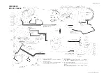
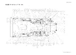
Страница 91: ...n FPC 半田ブリッジにて接続 Connected with soldering bridge GMR FPC ジャイロ FPC Gyro FPC A B a b 1 A B 2 フラッシュ書き込み FPC FPC for the flash memory 絶縁処理をすること Insulate FPC ブザー フォーカス機能切替 Function change SW AF モード AF mode 橙 Orange 白 橙 白 White VR on off 灰 Gray 黄 Y el lo w 黒 M 環検出 Rotation detection for MF ring 絶対距離エンコーダ FPC Absolute focal distance encoder FPC Range A C A C 1 A B ジャイロ基板部組 点線内の部材を 1 組として A B どちらか選択す...

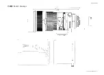
Страница 92: ...JAA33751 R 3646 A L1 AF S VR ED 300 2 8G IF 外観図 Sketch drawings ...

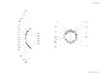
Страница 93: ...JAA33751 R 3646 A L2 AF S VR ED 300 2 8G IF 組立図 Structure of the Lens ...

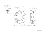
Страница 94: ...JAA33751 R 3646 A L3 AF S VR ED 300 2 8G IF ...

Страница 95: ...JAA33751 R 3646 A L4 AF S VR ED 300 2 8G IF ...

Страница 96: ...JAA33751 R 3646 A L5 AF S VR ED 300 2 8G IF ...

Страница 97: ...JAA33751 R 3646 A L6 AF S VR ED 300 2 8G IF ...

Страница 98: ...JAA33751 R 3646 A L7 AF S VR ED 300 2 8G IF ...

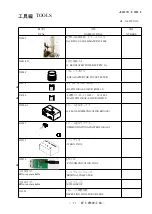
Страница 99: ...点検 調整ソフト ADJ FD FOR AF S 300VR IBM 3 5 J18380 VR 調整ソフト AF S 300VR FD IBM3 5 VR ADJ FD FOR AF S 300VR IBM3 5 J15306 1 AF I通信ボックス AF I LENS COMMUNICATION BOX CE J15307 AF I通信アダプター COMMUNICATION ADAPTER FOR AF I J15355 スイッチ工具 SW BOX TOOL J15416 通信工具 4 PIN COMUNICATION TOOL 工具設定なし RJNo is not available パーソナルコンピュータ PERSONAL COMPUTER 工具設定なし RJNo is not available オシロスコープ OSCILLOSCOP J15380 VRレンズ調整装置 INSP...

Страница 100: ...313 VRユニット固定工具 VR FIX TOOL FOR 3G AF S VR 300 2 8G OS 30MF ドライサ フ OS 30MF DRY SERF OS 30MF OIL BARRIER I 40 AFレンズ用グリ ス I 40 GREASE FOR AF LENS EDB0011 ネシ ロック 赤 1401C SCREW LOCK 1401C C 8008B セメダイン 8008 黒 CEMEDINE 8008 BLACK GE 8 AFレンズ用グリースGE8 GREASE FOR AF LENS GE 8 EBB8041 スクアグリ スG7813 GREASE G7813 L 241 ロックタイト 241 青 LOCTITE 241 EDZ4113 ボンド G103 BOND G103 F 890 ドライルーブ F 890 DRILUBE F 890 G92KA フロ...

Отзывы: