


18
REPAIR GUIDE
FFB Brake Motors Maintenance Guide
5287 en - 2019.07 / d
7 - REPAIR GUIDE
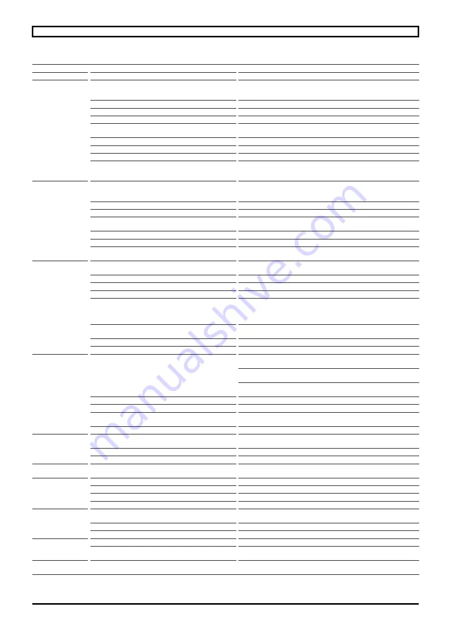
Incident
Possible cause
Remedy
Abnormal noise
From motor or driven machine?
Disconnect the motor from the driven device and test the motor alone
Noisy brake motor
Mechanical cause:
if the noise persists after powering
off
- Vibrations
Check that the key complies with the type of balancing
- Check the condition of the bearings
- Faulty bearing
- Change the bearings as soon as possible
- Sensor extension (item
1401
) fitted improperly
- See adjustment § 6.6
- Mechanical friction: ventilation, coupling
- Check and change the faulty part
Electrical cause:
if the noise stops after power drops
- Check the supply at the motor terminals
- Check the drive setting
- Normal voltage and 3 phases balanced
- Check the plate connection and strip tightening
- Abnormal voltage
- Check the supply line
- Unbalance of phases
- Check the resistance of windings
Other possible causes:
- bad drive setting
- drive malfunction
Refer to the drive manual
Abnormal motor
heating
- Faulty ventilation
- Check the environment
- Clean the ventilation cover and the cooling fins
- Check the fitting of the fan onto the shaft
- Faulty supply voltage
- Check
- Strip coupling error
- Check
- Overload
- Check the intensity absorbed with respect to that indicated in the motor
information plate
- Partial short circuit
- Check electrical continuity of the windings and/or the installation
- Phase unbalance
- Check the resistance of windings
Other possible causes:
- bad drive setting
Refer to the drive manual
Motor does not start
Empty:
- Mechanical blocking
- Release the brake and motor powered off:
check by hand that the shaft turns freely
- Power supply line interrupted
- Check the fuses, electric protection, starting device
- Position return (drive message)
- Check the wiring, drive setting, operation of the position sensor
- Thermal protection
- Check
In charge:
- Unbalance of phases
Powered off:
- Check the rotation direction (order of the phases)
- Check the resistance and continuity of the windings
- Check the electric protection
- Drive
- Check the setting, dimensioning (Max current delivered by the speed
drive)
- Position return (drive message)
- Check the wiring, drive setting, operation of the position sensor
- Thermal protection
- Check
The brake does not
release
- The voltage is present at the coil's terminals
The air gap is too big, the yoke does not attract the armature
- Adjust and check disc wear
The voltage is too low U < 0.8Un
- Restore the voltage to its nominal value
The coil is off, its resistance is infinite
- Change the complete brake unit or the coil
- The lever rod is in abutment on the cover
- See adjustment section 6.1 ref.
1406
- Mobile parts are stuck
- Remove, clean, and look for the cause of sticking
- No more voltage at the coil terminals
The cell is inoperative
- Test it
- Drive
- Check that the brake supply is separate from the motor's
The call time is too
long
- Check the voltage at the coil terminals
The voltage is too low U < 0.8Un (Un: according nominal power supply)
- Restore the voltage to its nominal value
- The air gap is too wide
- Readjust
- The braking moment has increased
- Return to the initial setting or consult
The drop time is too
long
- Check that the power off is performed on the direct
- Connect the cell as per the mark (A) power off on the direct
The brake is noisy
when released
- Irregular or excessive air gap
- Remove if necessary and clean (see §4)
- Foreign material in the air gap
- Clean
- Extension shaft
1401
fitted incorrectly
- See encoder reassembly section 6.6
- Drive
- Check that the brake supply is separate from the motor's
The braking moment
is insufficient
- The friction faces are not clean and dry
- Clean the friction faces
- Redefine the braking moment
- Pollution due to environment
- Clean friction faces. If disc is marked, replace it
- The disc is worn
- Change the disc
The brake is applied
(drops) but braking
is weak
- Insufficient spring pressure
- Check pad wear. Increase the number of springs
- Correct spring pressure
- Check the surface wear of the armature
- Use a blower to clean dust due to friction
Permanent pad
friction
- The air gap is insufficient
- Adjust the air gap
Содержание LEROY-SOMER FFB Series
Страница 1: ...2019 07 d en Maintenance Guide Reference 5287 en Maintenance Guide Brake motors FFB...
Страница 22: ...22 CONNECTION DIAGRAMS FFB Brake Motors Maintenance Guide 5287 en 2019 07 d NOTES...
Страница 23: ...23 CONNECTION DIAGRAMS FFB Brake Motors Maintenance Guide 5287 en 2019 07 d NOTES...


