Drive parameters Communications
Commander S100 User Guide
49
P0.05 =
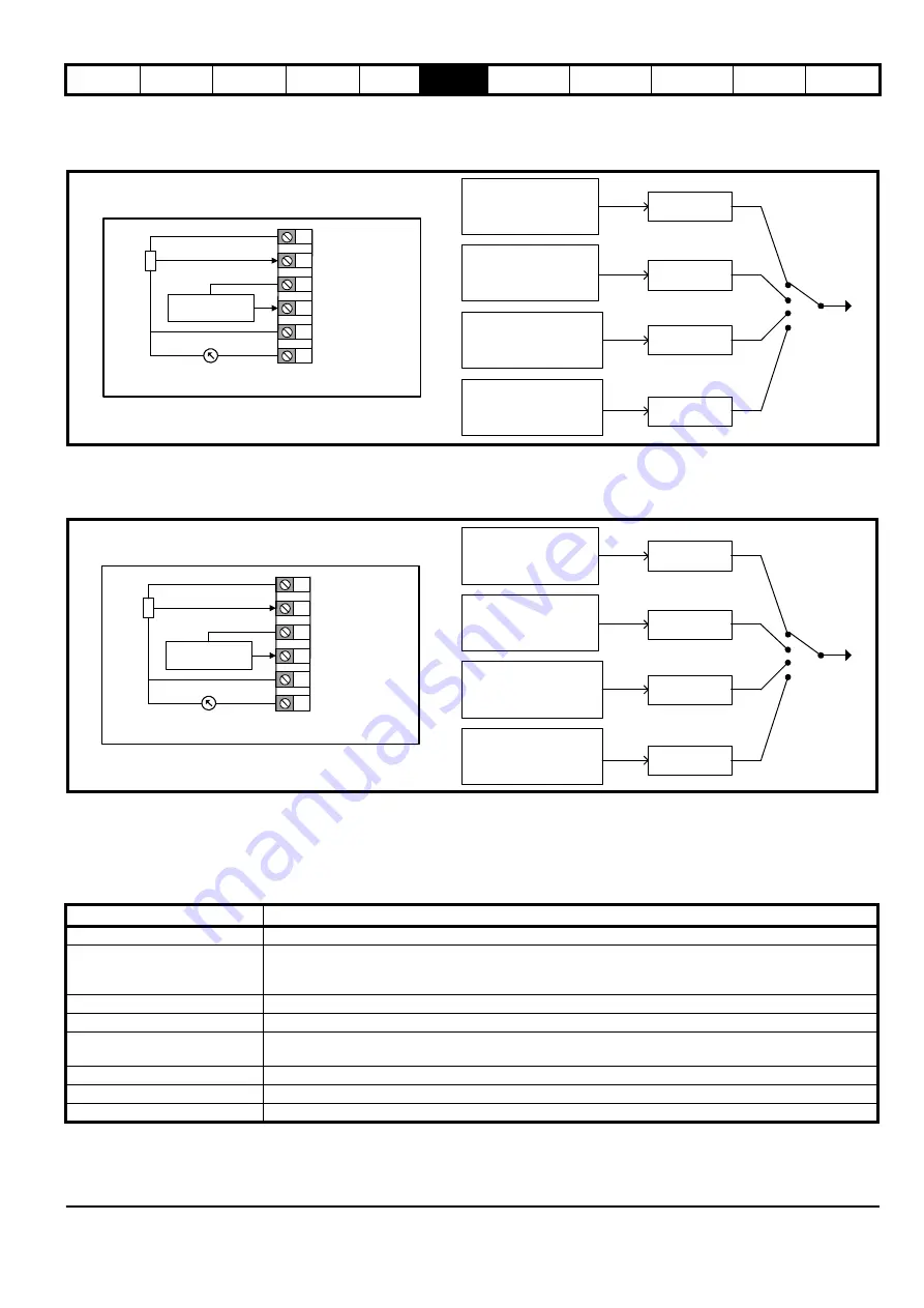
PID with Current Feedback
& Voltage Reference (8)
A current input on analog input 2 provides feedback to the PID controller where 4 mA = 0 % and 20 mA = 100 %
.
A voltage input on analog input 1
provides the PID with a reference where 0 V = 0 % and 10 V = 100 %. The PID output is used as the frequency reference. For more details on PID
setup, refer to section 7.3.5
P0.05 =
PID with Feed Forward
(9)
Current input on analog input 2 provides the PID Feedback for the PID Controller. A feed forward term is controlled by a voltage input on analog
input 1
.
The PID reference in this configuration is set by
PID Fixed Reference Setpoint 1
(P5.01). The PID output is used as the frequency reference.
For more details on PID setup, refer to section 7.3.5
.
6.3 Running, stopping and controlling motor direction
The user is able to provide a range of signals that instruct the drive to run and the direction to rotate the motor. These signals can be supplied with the
control terminals, the keypad buttons or a
Binary Control Word
(P4.18) via communications. The signals that can be provided to the drive are listed in
Table 6-2 Input Functions
The user can only use the keypad buttons to provide Run, Stop and Jog Forward signals, but the Stop button will only stop the drive if the keypad
buttons were used to run the drive.
Not Configured
Not Configured
Not Configured
PID Percentage (P1.19)
Reference 1
Reference 2
Reference 3
Reference 4
1
2
3
4
+10 V Output
0 V
5 0 V
6 Analog output
PID with Voltage reference (P0.05 = 8)
PID Feedback
PID Reference
0-10 V Input (AI1)
4-20 mA Input (AI2)
Not Configured
Not Configured
Not Configured
PID Percentage (P1.19)
Reference 1
Reference 2
Reference 3
Reference 4
1
2
3
4
+10 V Output
0 V
5 0 V
6 Analog output
PID with Feed Forward (P0.05 = 9)
PID Feedback
PID Feed Forward
0-10 V Input (AI1)
4-20 mA Input (AI2)
Function
Description
Hardware Enable (1)
If configured the drive will not run without an active Hardware Enable signal.
Run Permit (Not Stop) (4)
If configured the drive will not run without an active Run Permit signal. Run Forward (2), Run Reverse (3) and
Run (16) signals are held active allowing for a momentary press (button operated), so in order to stop the drive
the Run Permit signal must be removed.
Run Forward (2)
When active the drive will run forward at the selected reference.
Run Reverse (3)
When active the drive will run reverse at the selected reference.
Run (16)
When active the drive will run at the selected reference. The direction is forward by default, but this can be
changed to reverse if there is an active Reverse (17) signal.
Reverse (17)
When active the motor direction will reverse if there is an active Run (16) signal.
Jog Forward (18)
When active the drive will run forward at the
Jog Frequency
(P2.13).
Jog Reverse (19)
When active the drive will run reverse at the
Jog Frequency
(P2.13).
Содержание COMMANDER S100
Страница 118: ...0478 0650 02...


