


4
Installation Instructions
§
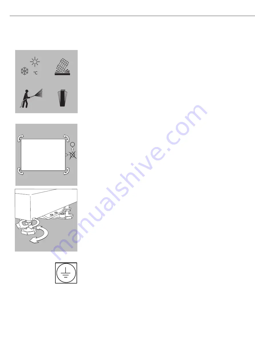
Prepare a suitable place of installation for the weighing platform. The place of
installation should be dry, level and even. The allowable operating temperature range
is -10°C to +40° (14°F to 104°F). The permissible load that can be carried by the
chosen working surface must be sufficient for both the weighing platform and any
load placed on the platform.
If you need to use the weighing platform in areas exposed to heavy traffic (e.g., forklift
trucks), you should install a protective frame, consisting of angular braces, around the
weighing platform.
Do not expose the weighing platform unnecessarily to extreme temperatures, moisture,
shocks, or vibration that could result in damage.
§
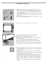
The air bubble must be centered within the circle on the level indicator.
§
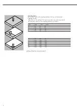
Level the weighing platform using the leveling feet as described below:
§
Check to ensure that all leveling feet rest securely on the work surface.
> Each of the leveling feet must support an equal load.
§
Loosen the lock nuts on the leveling feet using a 19-mm open-end wrench (spanner).
> Adjusting the leveling feet:
To raise the weighing platform, extend the leveling feet (turn clockwise).
To lower the weighing platform, retract the leveling feet (turn counterclockwise .
§
After leveling the weighing platform, retighten the lock nuts securely as described
below:
Low-capacity platforms (1 load cell): tighten the lockouts against the platform frame;
high-capacity platforms (4 load cells): tighten the lock nuts against the platform feet.
§
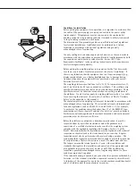
If the weighing platform is in a hazardous area/location, it must be grounded (i.e., an
equipotential bonding conductor must be connected). This connection should be made
by a trained technician.
All Combics weighing platforms are equipped with a connector for the grounding
conductor.
This is located either below the load pan, on the junction box, or on the lower frame of
the weighing platform. The position is marked in each case by the symbol shown here,
indicating the grounding (earthing) connection.
The grounding conductor is connected to a threaded bolt or terminal screw, or a bore
hole is provided. If a bore hole is provided, use a stainless steel screw and nut to
connect the grounding conductor. Use of a tooth lock washer is recommended, to
prevent the screw from coming loose. The wire used for the grounding conductor
should have a cross-sectional diameter of at least 4 mm
2
, with a suitable ring lug
attached.
Connect all equipment, including peripheral devices, to the equipotential bonding
conductor
Содержание Sartorius Combics CAPXS Series
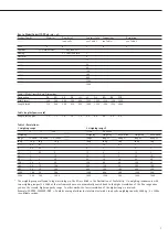
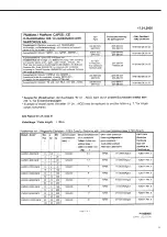
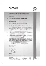
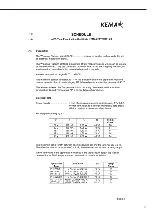
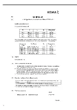
Страница 13: ...12 EC Type Approval Certificate...
Страница 14: ...13...
Страница 15: ...14...
Страница 16: ...15...
Страница 17: ...15...
Страница 18: ...16...
Страница 19: ...17...
Страница 20: ...18...
Страница 21: ...19...
Страница 22: ...20...
Страница 23: ...21...
Страница 24: ...22...
Страница 25: ...23...
Страница 26: ...24...
Страница 27: ...25...
Страница 28: ...26...
Страница 29: ...27...
Страница 30: ...28...
Страница 31: ...29...
Страница 32: ...30...
Страница 33: ...31...