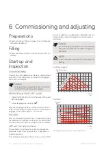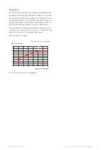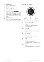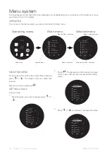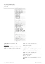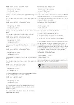
MENU 21 - BYPASS MAX
Setting range: 1 - 10 °C
Default value: 3 °C
Here you set control of the bypass damper.
The damper opens when the temperature is 1°C above
the set value in User menu, menu 1 - "Temperature",
provided that
• the exhaust air temperature is higher than the outdoor
air temperature
• the outdoor air temperature is above the set value in
Service menu, menu 29 - "Stop bypass t3".
TIP
In order to achieve even control, the temperat-
ure at fully open damper should be approx. 3°C
above the set temperature in User menu, menu
1 - "Temperature".
MENU 22 - WATER CONTROL
Setting range: 1 - 250 sec.
Factory setting: 20 sec.
Here you set the control of the waterborne re-heater
with a motor valve. The lower the value, the faster the
valve will exercise control.
MENU 23 - POWER REGULATOR
Setting range: 1 - 30 min
Factory setting: 3 min
Here you set the control of the electrical air heater
(EAH 21) or re-heater. The lower the value, the faster
the valve will exercise control.
MENU 24 - FROST REDUCTION
Setting range: 0 - 10 °C
Default value: 3 °C
Here you set the extract air temperature at which the
supply air flow will be reduced to prevent damage to
the heat exchanger (EP26) due to freezing.
The supply air flow is gradually reduced until the set
value is reached. This function is only active if the set
value is greater than 0°C.
NOTE
Can cause negative pressure in the house.
MENU 25 - FROST
Setting range: "On" and "off"
Factory setting: "Off"
Waterborne re-heater with motor valve required.
Select "on" if the re-heater has a frost sensor.
TIP
Should the re-heater have a frost sensor in or-
der to avoid damage? In order for the installa-
tion to work? In order...
MENU 26 - FROST
Setting range: 0 - 10 °C
Default value: 5 °C
Waterborne re-heater with motor valve required.
Here you set the temperature at which the waterborne
re-heater will defrost.
MENU 27 - AUXILIARY RELAY R9
Setting range: 0 - 5
Default value: 0
Here, you can force control the various components in
the HRV unit.
NOTE
Forced control is only intended to be used for
troubleshooting purposes. Using the function
in any other way may cause damage to the
components in the installation.
The relay is switched off.
0
The relay is engaged, provided the installation is in
use. The relay can be used, for example, to open or
close the supply air or exhaust air damper.
1
The relay is engaged when there is a need for addi-
tional heat or when there is a wish to operate the
circulation pump, when heating with waterborne
reheating is required.
2
The relay is engaged on filter alarm. This can be used
to activate an external alarm.
3
The relay is engaged when there is a need for extra
cooling. This function is used if the installation has
an electrical air heater (EAH 21) installed.
4
NIBE GV-HR 120-400
Chapter 8 | Control - Menus
26
Содержание GV-HR 120
Страница 1: ...IHB EN 2110 2 531842 INSTALLER MANUAL HRV unit NIBE GV HR 120 400 LEK...
Страница 2: ......

