background image

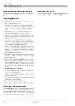
Insert a screwdriver and turn the pump rotor.

Screw in the venting screw.

Start FIGHTER 1127 and check that the circulation pump
functions.

It is usually easier to start the circulation pump with FIGHTER
1127 running, switch (8) in position ”

1

”. If helping the circu-

lation pump to start is performed with FIGHTER 1127 run-
ning, be prepared for the screwdriver to jerk when the pump
starts.

Indications

NOTE

Work behind panels secured by screws may only be

carried out under the supervision of a qualified install-

ation engineer.

Alarm lamp flashes and the text ”HP/MS–alarm”is dis-
played

AT HP/MP alarm: Set the motor protection to manual mode
and restart the heat pump.

Bad circulation in the heating medium circuit.

Cause:

Check the heating medium pump (16). Open any
radiator thermostats. Check that the particle filter
is not blocked.

Action:

If the alarm lamp still flashes the motor cut-out has tripped due
to the following causes.

Dropped phase or temporary mains disturbance.

Cause:

Check the fuses.

Action:

Overloaded compressor (27).

Cause:

Call qualified service personnel.

Action:

Mechanical fault on the compressor (27).

Cause:

Call qualified service personnel.

Action:

Defective motor protection (26).

Cause:

Call qualified service personnel.

Action:

Fine-wire fuse on relay card (29) has blown.

Cause:

Replace the fuse.

Action:

NOTE

The fault status must not be repeatedly reset, as there

is a risk of overheating the motor windings.

Alarm lamp flashes and the text ”LP–alarm”is displayed

Start up of cold installation

Cause:

Use ”Electric boiler mode”.

Action:

Bad circulation in brine system due to inferior ven-
ting/low pressure or ice (if ice has formed the brine
pump (35) will be warm).

Cause:

Vent and top up the fluid. Wait a few hours.

Action:

Brine pump (35) not running.

Cause:

Check the brine pump.

Action:

Lack of heating medium or other fault in the coo-
ling circuit.

Cause:

Call qualified service personnel.

Action:

Iced evaporator due to too low antifreeze concent-
ration.

Cause:

Check the brine’s freezing point.

Action:

After corrective action, in the display check that the differ-
ence between "

Brine In

" and "

Brine O

" is 2 – 5°C when

the compressor is operating. (See "Control –Information
available on the display", point 4.)

Once the fault cause has been rectified set switch (8) to ”

0

and then to ”

1

”.

Draining, heat medium side

Close the shut-off valves in heating medium system. Now
open the drain valve (76). A small amount of water runs out,
however, to fully empty the heating medium side requires
the connector that joins the heating medium side and the
connection on the heat pump ”HM-flow” to be loosened a
little to allow air to enter so the remaining water can run
out. When the heating medium side is empty the requisite
service can be carried out.

Draining, collector side

When replacing the brine pump or drive side or when
cleaning the pump, the shut-off valves in the brine system
should be closed. The hose between the top of the evapor-
ator and the brine pump is loosened on the evaporator. The
loose hose end can now be bent down and emptied in a
small bowl. Now loosen the connection to ”KB-in” a little
to allow air to enter so the heat pump’s brine side is emptied
completely. When the circuit is empty the requisite service
can be carried out.

If the operating disturbance cannot be rectified by means of the above, an installation engineer should be called.

FIGHTER 1127

32

Miscellaneous

Dealing with malfunctions

Содержание FIGHTER 1127

Страница 1: ...INSTALLATION AND MAINTENANCE INSTRUCTIONS MOS GB 0737 2 FIGHTER 1127 031153 FIGHTER 1127 2 0 2 1 R 0 LEK...

Страница 2: ...LEK LEK LEK LEK LEK LEK LEK LEK LEK LEK...

Страница 3: ...n of room temperature sensor RG 20 17 Connecting the outside sensor 17 Connecting the supplied hot water temperature sensor with floating condensing 18 Connecting supplied external circulation pumps 1...

Страница 4: ...ominal temperature diff 2 5 C Temperature heat medium in out ____ ____ Pump setting ___ Nominal temperature diff 5 10 C Settings Basic setting Menu Basic setting Menu 60 10b HP min 2 Room 300 10b Add...

Страница 5: ...n of flow changes in the refrigerant system Even the external systems brine and heating medium change direction by the external pumps starting for opposite circulation The heat energy is now emitted t...

Страница 6: ...p and additional heater when necessary if the latter is fitted B Function keys Channel Selection of the window menu VB Fram 49 50 C Varmvatten 51 C Increase Increase of current value VB Fram 49 50 C V...

Страница 7: ...g Addition ready to start if needed Hot water charging cuts in if needed LEDs Continuous light Room heating coo ling Continuous light during hot water char ging Hot water Flashing Steady light Additio...

Страница 8: ...om temperature Changing the room temperature manually If you want to temporarily or permanently increase or lower the indoor temperature in relation to the previous heat set ting turn the Increase red...

Страница 9: ...ated flow temperature Hot water Indication of the hot water temperature 2a Outdoor 14 C Room 20 5 20 C Outdoor Current outdoor temperature Room Current room temperature Only shown if a room sensor is...

Страница 10: ...eating Press the Channel button to continue 4b WW in 37 53 C HW stop 52 C This menu is a sub menu to menu 4 Setting HW stop Press the Increase button in menu 4a A cursor will ap pear within the bracke...

Страница 11: ...max levels Sensor placement and pump flow observed 7 HP start 10 HP off HP start Counts the starts of the heat pump cumulative HP off Shows the operating mode HP off HP on HP start in X minutes or Hi...

Страница 12: ...nsors The room sensor is used to compensate the deviation in room temperature Guideline values for collectors Recommended collector length must be adjusted according to local conditions The length of...

Страница 13: ...by the system is obtained Settings 10a GM GM Degree min P Current value for number of degree minutes For example this value can be changed to accelerate the start of heating cooling production Settin...

Страница 14: ...re is then supplemented with EP Selectable operating modes Compressor operation 0 1 step EP drift after acknowledgement 1 16 Cal Out 0 Room 0 Brine In 0 Brine O 0 Cal Out P Calibration of outside sens...

Страница 15: ...stops at half R C below Ex ample At R 2 at FIGHTER 1127 and 22 C on RG 20 cooling starts at 24 C and stops at 23 C Default setting is Off In cooling mode with the room sensor RG20 select Cooling On Th...

Страница 16: ...ilable pressure setup 0 20 80 40 Fl de 60 1 0 k W 0 20 80 40 Fl de 60 100 100 0 0 07 0 13 0 21 l s 0 27 0 35 0 42 0 48 0 69 0 62 0 55 0 0 07 0 13 0 21 l s 0 27 0 35 0 42 0 48 0 69 0 62 0 55 1 2 3 1 2...

Страница 17: ...k VVB ACK is fully charged the shuttle valve VXV switches over to the heating circuit The heat pump is then controlled by the outdoor sensor in combination with the built in flow sensor and room tempe...

Страница 18: ...tallation and wiring must be carried out in accord ance with the stipulations in force Supply cables to the heat pump are placed in the cable duct on the left of the unit Cables for external sensors m...

Страница 19: ...e for example by placing in a niche between shelves behind a curtain above or close to a heat source or the like Also consider any draughts from exterior doors Neither must the unit be affected by sol...

Страница 20: ...rated 22 156 156 X7 Connection of accessory VST 12 Connect the accessory VST 12 to the terminal block X6 6 positions 2 to 5 as illustrated 6 X6 F1127 mitsubishi A 22 21 30 Connection of flow monitor F...

Страница 21: ...ling pump are now operating together Let the liquid circu late via the mixing vessel until there are no more air bubbles in the liquid in the return hose Now stop the brine pump by resetting Brine pum...

Страница 22: ...lar attention should be given to the level in the brine system when initially using the heat pump Some topping up may be necessary 9 Read the heating medium temperatures WW out and WW in The differenc...

Страница 23: ...10 9 8 7 6 5 4 3 2 1 1514 13 12 11 10 8 7 6 5 4 3 2 1 40 C UTETEMPERATUR 10 0 10 5 5 30 40 50 60 70 C FRAMLEDNINGSTEMPERATUR 20 30 F RSKJUTNING V RMEKURVA 2 9 V RMEKURVA V RMEKURVA 5 5 F RSKJUTNING V...

Страница 24: ...positions 2 0 2 1 R 0 LEK F1127 mitsubishi AK 8kW 95 68 6 22 9 21 30 29 26 13 97 14 2 K E L K E L 4 86 71 70 89 5 94 35 77 76 16 96 87 LEK 18 17 153 41 33 27 42 7 48 49 65 65 19 FIGHTER 1127 22 Misce...

Страница 25: ...Service connection low pressure 42 Expansion valve heating mode 48 Expansion valve cooling mode 49 Safety valve collector side 52 Particle filter 63 Drying filter 65 Contactor compressor start 68 Conn...

Страница 26: ...Electrical circuit diagram FIGHTER 1127 24 Miscellaneous Technical specifications...

Страница 27: ...25 FIGHTER 1127 Miscellaneous Technical specifications...

Страница 28: ...FIGHTER 1127 26 Miscellaneous Technical specifications...

Страница 29: ...27 FIGHTER 1127 Miscellaneous Technical specifications...

Страница 30: ...98 100 100 100 30 100 67 5 4 71 70 2 0 2 1 R 0 HM flow 49 50 C Hot water 51 C 598 525 525 625 2 0 2 1 R 0 HM flow 49 50 C Hot water 51 C 30 50 1000 75 198 100 100 100 30 100 67 Leave space free to the...

Страница 31: ...59526447 230V HEJSAN PC 0017NIB DK 50Hz IP 44 TF 110 Class H Max 10bar 2 5uF 45 0 20 65 0 30 90 0 40 1m A P W LEK GRUNDFOS Type UPS 25 60 130 P N 59526447 230V HEJSAN PC 0017NIB DK 50Hz IP 44 TF 110...

Страница 32: ...W Power external circulation pumps 35 28 mm Connection Brine male 28 mm Connection heating medium male 1 9 1 79 kg Refrigerant quantity R407C 0 65 0 48 l s Brine flow 15 23 kPa Pressure drop evaporato...

Страница 33: ...ing Incorrect setting of the Curve slope and or Increase reduce room temperature Cause Adjust the setting Action NOTE The product s serial number should always be stated with all correspondence with N...

Страница 34: ...low pressure or ice if ice has formed the brine pump 35 will be warm Cause Vent and top up the fluid Wait a few hours Action Brine pump 35 not running Cause Check the brine pump Action Lack of heatin...

Страница 35: ......

Страница 36: ...6998 E mail info nibeboilers nl www nibeboilers nl V lund Varmeteknik Filial af NIBE AB Brog rdsvej 7 6920 Videb k Tel 97 17 20 33 Fax 97 17 29 33 E mail info volundvt dk www volundvt dk NIBE Systemte...

Отзывы: