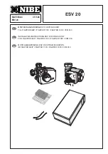


ESV 20
FIGHTER 360P
11
GB
LEK
+2
0
-2
A B
A B
A B
I II III
I II
I II
In
s
t
a
ll
as
follow
s
.
■
Empty the w
a
ter cylinder fir
s
t, if thi
s
i
s
filled with
w
a
ter. Un
s
crew the pl
u
g (61) in the di
s
hed end of
FIGHTER 360P. In
s
t
a
ll the
su
pplied pl
as
tic pipe
where the pl
u
g w
as
previo
us
ly fitted.
Pipe connections
■
The extr
a
circ
u
l
a
tion p
u
mp (VBP2)
a
nd
s
h
u
nt v
a
lve
(SV-V2)
a
re po
s
itioned in
a
su
it
ab
le
a
re
a
o
u
t
s
ide of
FIGHTER 360P. From the co
u
pling on the fitted
pl
as
tic pipe ro
u
te the pipe to the
s
h
u
nt v
a
lve. The
ret
u
rn pipe from he
a
ting
s
y
s
tem 2 i
s
connected to
the
s
h
u
nt v
a
lve
as
well
as
the ret
u
rn pipe from
he
a
ting
s
y
s
tem 1,
s
ee fig
u
re.
■
The two
su
pplied temper
a
t
u
re
s
en
s
or
s
a
re fitted in
connection to he
a
ting
s
y
s
tem 2
as
ill
us
tr
a
ted in the
fig
u
re.
The flow
s
en
s
or (FS2) i
s
fitted on the pipe
b
etween
the
s
h
u
nt v
a
lve
a
nd the circ
u
l
a
tion p
u
mp (VBP2).
The ret
u
rn
s
en
s
or (RG2) i
s
fitted on the pipe from
he
a
ting
s
y
s
tem 2.
■
Cont
a
ct p
as
te
a
nd in
su
l
a
tion
a
ro
u
nd the
s
en
s
or
a
nd pipe m
us
t
b
e
us
ed d
u
ring in
s
t
a
ll
a
tion to o
b
t
a
in
the correct temper
a
t
u
re me
asu
rement. NOTE!
Incorrect in
s
t
a
ll
a
tion c
a
n p
u
t f
u
nction
a
lity
a
t ri
s
k.
LEK
61
Värmesystem 2
Värmesystem 1
61
S
V-V2
FG2
VBP2
RG2
AV
AV
LEK
LEK
Ret
u
rn
He
a
t p
u
mp
Flow
AV
Sh
u
toff v
a
lve
FG2
Flow
s
en
s
or 2
RG2
Ret
u
rn
s
en
s
or 2
SV-V2 Sh
u
nt v
a
lve 2
VBP2 Circ
u
l
a
tion p
u
mp 2
He
a
ting circ
u
it 2
He
a
ting circ
u
it 1


