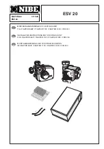
Nibe ESV 20 Скачать руководство пользователя страница 1

MAV 0538-4

411546

ESV 20

R

ESV 20 

DE

GB

SE

MONTERINGSANVISNING ESV 20 EXTRA SHUNT
TILL FIGHTER 360P / FIGHTER 1130 / FIGHTER 1230 / VVM 240

INSTALLATION INSTRUCTIONS ESV 20 EXTRA SHUNT
FOR FIGHTER 360P / FIGHTER 1120 / FIGHTER 1220 / VVM 240

MONTAGEANWEISUNG ESV 20 EXTRA MISCHVENTIL
IM FIGHTER 360P / FIGHTER 1120 / FIGHTER 1220 / VVM 240

LEK

LEK

G

R

U

N

D

FO

S

Ty

p

e

UP

S

25 - 60

1

3

0

P/N

:59526447

2

3

0V

-

HEJ

S

A

N

PC;0017NIB

D

K

50Hz

IP

  44

TF  110

Class  H

Max.

  10bar

2.5uF

45

0.20

65

0.

3

0

90

0.40

1m(A)

P,

(W

)

Содержание ESV 20

Страница 1: ...STALLATION INSTRUCTIONS ESV 20 EXTRA SHUNT FOR FIGHTER 360P FIGHTER 1120 FIGHTER 1220 VVM 240 MONTAGEANWEISUNG ESV 20 EXTRA MISCHVENTIL IM FIGHTER 360P FIGHTER 1120 FIGHTER 1220 VVM 240 LEK LEK GRUNDF...

Страница 2: ......

Страница 3: ...mesystem 2 avser det v rmesystem som arbetar med l gre temperatur Vattenfl det i de tv v rmesystemen tillsammans b r ej verstiga 1700 l h Sifferbeteckningar i f ljande text refererar till avsnittet Ko...

Страница 4: ...plas till shuntventilen samt till returledningen fr n v rme system 1 se bild De tv medf ljande temperaturgivarna monteras i anslutning till v rmesystem 2 enligt bild Framledningsgivaren FG2 monteras p...

Страница 5: ...t jordstift p kopplings plinten till v nster om kompressorkondensatorn Den andra nden p 5 ledarkabeln shuntmotorn och v rmeb rarpumpen kopplas in i kopplingsdosan enligt nedanst ende bild Kopplingsdos...

Страница 6: ...plats utanf r VVM 240 Shuntventilen SV V2 placeras p framledningen efter VVM 240 f re f rsta radiatorn p v rmesystem 1 Returledningen fr n v rmesystem 2 kopplas till shuntventilen samt till returledni...

Страница 7: ...sluts till position 7 och 8 p effektvaktskortets 2 nedre plint Returgivare 2 kopplas in till position 5 och 6 p samma kort Anv nd medf ljande rundstiftshylsor f r skarvning mellan tv ledaren och givar...

Страница 8: ...st pannvattenk rlet v rmesystemet om detta r vattenfyllt Den extra v rmeb rarpumpen VBP2 placeras p l mplig plats utanf r FIGHTER 1130 1230 Shuntventilen SV V2 placeras p framledningen efter v rmepump...

Страница 9: ...uts till position 7 och 8 p effektvaktskortets 2 nedre plint Returgivare 2 kopplas in till position 5 och 6 p samma kort Anv nd medf ljande rundstiftshylsor f r skarvning mellan tv ledaren och givaren...

Страница 10: ...is EKXX eller LiYY enligt f ljande Den givare som anv nds som framledningsgivare 2 ansluts till position 7 och 8 p effektvaktskortets 2 nedre plint Returgivare 2 kopplas in till position 5 och 6 p sam...

Страница 11: ...827 2 1 bar 3 0 4 VARNING DATASKY LT 123456 SERIENR 123456 VV KV L E K Art nr 611 2 1 bar 3 0 4 FIGHTER 360P FIGHTER 1130 VVM 240 FIGHTER 1230 Plats f r medf l jande rel kort Jordstift Plats f r medf...

Страница 12: ...system 2 refers to the heating system that works at the lowest temperature The combined water flow in the two heating systems should not exceed 1700 l h The number designations in brackets in the fol...

Страница 13: ...s well as the return pipe from heating system 1 see figure The two supplied temperature sensors are fitted in connection to heating system 2 as illustrated in the figure The flow sensor FS2 is fitted...

Страница 14: ...he connection box as shown in the figure below The connection box can be mounted on a wall The sensors are connected with a two wire cable for example EKXX or LiYY as follows The sensor used as the fl...

Страница 15: ...s positioned on the flow pipe after VVM 240 before the first radiator on heating sys tem 1 The return pipe from heating system 2 is connected to the shunt valve as well as the return pipe from heating...

Страница 16: ...to positions 5 and 6 on the same card Use the supplied round pin adapters for the splice between the two wire cable and the sensor Electrical connection NOTE All electrical connections should be made...

Страница 17: ...s positioned on the flow pipe after the heat pump before the first radiator on heating system 1 The return pipe from heating system 2 is connected to the shunt valve as well as the return pipe from he...

Страница 18: ...ed to positions 5 and 6 on the same card Use the supplied round pin adapters for the splice between the two wire cable and the sensor Electrical connection 4 X4 1 X6 1 Return sensor 2 Flow sensor 2 2...

Страница 19: ...ions 7 and 8 on the load monitor card 2 lower terminal Return sensor 2 is connected to positions 5 and 6 on the same card Use the supplied round pin adapters for the splice between the two wire cable...

Страница 20: ...1 bar 3 0 4 VARNING DATASKY LT 123456 SERIENR 123456 VV KV L E K Art nr 611 2 1 bar 3 0 4 FIGHTER 360P FIGHTER 1120 VVM 240 FIGHTER 1220 Space for the supplied relay card Earth pin Space for the sup p...

Страница 21: ...ssen wird Unter Heizsystem 2 ist dann jener Heizkreis zu verste hen der mit niedriger Temperatur arbeitet Der gemeinsame Heizwasserfluss f r beide Systeme sollte keine 1700 l h berschreiten Die Beziff...

Страница 22: ...V V2 sowie an die R cklaufleitung des Heizsystems 1 angeschlossen Siehe Abbildung Die zwei mitgelieferten Temperaturf hler werden gem Abbildung am Heizsystem 2 montiert Dabei wird der Vorlauff hler FG...

Страница 23: ...n Der Vorlauff hler FG2 ist auf der unteren Klemmleiste in Position 7 und 8 w hrend der R cklauff hler RG2 in Position 5 und 6 auf der Steuerelektronik 2 anzuschlie en Zur guten Verbindung zwischen de...

Страница 24: ...n Das Mischventil SV V2 hinter dem VVM 240 im Vorlauf vor dem ersten Heizradiator des Heizsystems 1 einbauen Die R cklaufleitung vom Heizsystem 2 wird ans Mischventil SV V2 sowie an die R cklaufleitun...

Страница 25: ...n Klemmleiste in Position 7 und 8 w hrend der R cklauff hler RG2 in Position 5 und 6 auf der Steuerelektronik 2 anzuschlie en ist Zur guten Verbindung zwischen dem 2 poligen Leiter sowie dem F hler si...

Страница 26: ...Das Mischventil SV V2 hinter der W rmepumpe im Vorlauf vor dem ersten Heizradiator des Heizsystems 1 einbauen Die R cklaufleitung vom Heizsystem 2 wird ans Mischventil SV V2 sowie an die R cklaufleit...

Страница 27: ...Klemmleiste in Position 7 und 8 w hrend der R cklauff hler RG2 in Position 5 und 6 auf der Steuerelektronik 2 anzuschlie en ist Zwecks guter Verbindung zwischen dem 2 poligen Leiter sowie dem F hler s...

Страница 28: ...it 2 poligem Leiter z B EKXX oder LiYY wie folgt anzuschlie en Der Vorlauff hler FG2 ist auf der unteren Klemmleiste in Position 7 und 8 w hrend der R cklauff hler RG2 in Position 5 und 6 auf der Steu...

Страница 29: ...ar 3 0 4 VARNING DATASKY LT 123456 SERIENR 123456 VV KV L E K Art nr 611 2 1 bar 3 0 4 FIGHTER 360P FIGHTER 1120 VVM 240 FIGHTER 1220 Platz f r mitgelieferte Relaiskarte Erdungsstift Platz f r mitgeli...

Страница 30: ...ESV 20 28...

Страница 31: ......

Страница 32: ...H Am Reiherpfahl 3 29223 Celle Tel 05141 7546 0 Fax 05141 7546 99 E mail info nibe de www nibe de NIBE Energietechniek B V Postbus 2 4797 ZG WILLEMSTAD NB Tel 0168 477722 Fax 0168 476998 E mail info n...

Отзывы: