


ON
12345678
-X9
-X2
24
20
21
22
23
15
16
17
18
19
10
11
12
13
14
5
6
7
8
9
1
1
N
L
PE
PE
1
2
3
4
5
6
7
8
2
3
4
5
6
7
8
9
2
3
4
-X8
-X4
-X10
-X1
$$;
$$;
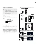
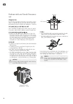
Connection of sensors and external adjust-
ment
Use cable type LiYY, EKKX or similar.
Flow temperature sensor, extra climate system
(BT2)
Connect the flow temperature sensor to AA5-X2:23-24.
Return line sensor, extra climate system (BT3)
Connect the return line sensor to AA5-X2:21-22.
Room temperature sensor, extra climate system
(BT50) (optional)
Connect the room temperature sensor to AA5-X2:19-20.
External adjustment (optional)
A potential free switch can be connected to AA5-
X2:17-18 for external adjustment of the climate system.
$$;
24
20
21
22
23
16
17
18
19
%7
%7
%7
([WHUQDO DGMXVWPHQW
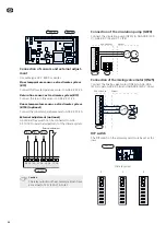
Caution
The relay outputs on the accessory card can have
a max load of 2 A (230 V) in total.
Connection of the circulation pump (GP20)
Connect the circulation pump (GP20) to AA5-X9:8 (230
V), AA5-X9:7 (N) and X1:3 (PE).
1
2
3
4
5
6
7
8
9
L
N
PE
3
2
1
(&6b(&6b
([WHUQDO
;
*3
$$;
Connection of the mixing valve motor (QN25)
Connect the mixing valve motor (QN25) to AA5-X9:6
(230 V, open), AA5-X9:5 (N) and AA5-X9:4 (230 V, close).
1
2
3
4
5
6
7
8
9
(&6b(&6b
([WHUQDO
$$;
41
%OXH
:KLWH
%URZQ
1
&ORVH
2SHQ
DIP switch
The DIP switch on the accessory card must be set as fol-
lows.
ON
12345678
-X9
-X2
24
20
21
22
23
15
16
17
18
19
10
11
12
13
14
5
6
7
8
9
1
1
N
L
PE
PE
1
2
3
4
5
6
7
8
2
3
4
5
6
7
8
9
2
3
4
-X8
-X4
-X10
-X1
AA5-S2
Climate system
4
3
2
ON
12345678
ON
12345678
ON
12345678
22
GB
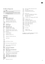
Содержание ECS 40
Страница 2: ......
Страница 13: ...13 SE ...
Страница 24: ...24 GB ...
Страница 35: ...35 DE ...
Страница 46: ...46 Elschema Wiring diagram Elektrischer schalt plan Sähkökytkentäkaavio ...
Страница 47: ......


