We reserve the right to make technical changes.
83050406cUK – Translation of the operating manual
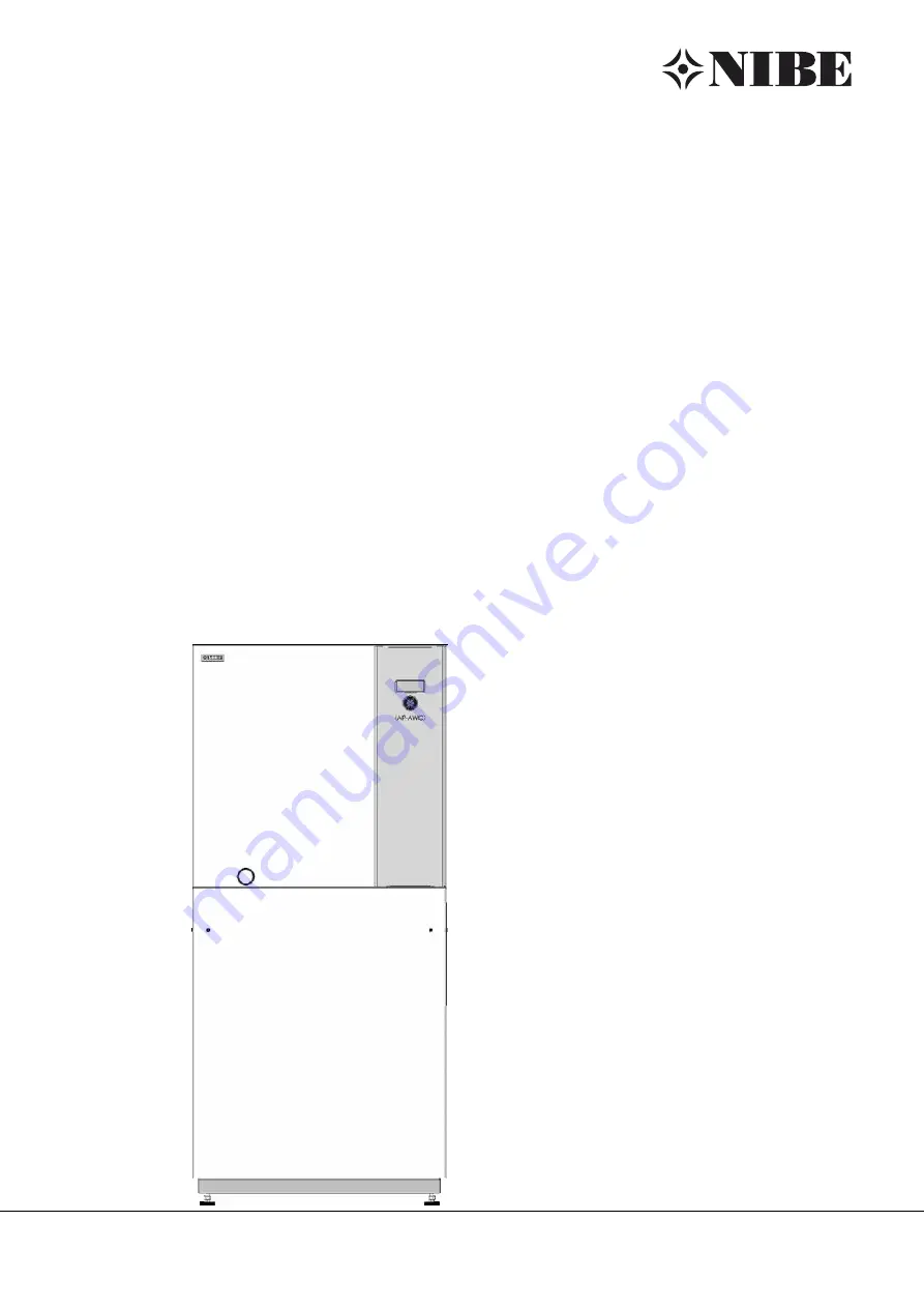
Operating Manual UK
Air / Water
Compact
Heat Pumps
NIBE
TM
AP-AW10
Страница 1: ...We reserve the right to make technical changes 83050406cUK Translation of the operating manual Operating Manual UK Air Water Compact Heat Pumps NIBETM AP AW10...
Страница 2: ...rs for the respective model This operating manual is intended only for persons assigned to work on or operate the unit Treat all constituent parts confidentially The information contained herein is pr...
Страница 3: ...t pump 15 Screen frame assembly 16 Wire mesh grille and weather rain guards assembly 16 Installation connection to heating circuit 17 Manometer 18 Discharge hot water safety valve and condensate disch...
Страница 4: ...aration of conformity Safety The unit is operationally safe when used for the intended purpose The construction and design of the unit conform to the state of the art all relevant DIN VDE regulations...
Страница 5: ...d also the intake air which is used as a source of heat must not contain any kind of corrosive components Components such as ammonia sulphur chlo rine salt sewer gas flue gases etc may cause damage le...
Страница 6: ...QR is mandato ry with air water heat pumps With brine water and wa ter water heat pumps a HQR may only be set up when a forward flow temperature of 35 C has been reached The HQR must record the total...
Страница 7: ...oling system technician Attention Check regularly to ensure that the condensate can drain out of the unit unobstructed To this end regularly check the condensate pan in the unit and the condensate dra...
Страница 8: ...ollows Inspect delivery for outwardly visible signs of damage Check to make sure that delivery is complete Any defects or incorrect deliveries must be claimed immediately Overview Technical data scope...
Страница 9: ...tention Do not tilt the unit more than a maximum of 45 in any direction To avoid damage during transport you should transport the unit to the final installation location in its original packaging with...
Страница 10: ...and lift the unit from the wooden pallet Transport with a hand truck Dispose of angle bracket transport and packaging material properly and in accordance with ecological principles Set unit on a stab...
Страница 11: ...ing the dummy plug included in the extra box Installation of the ventilation duct Converting from air blower on the right to air blower on the left Notice Note the air blow out direction of the unit B...
Страница 12: ...the two cable brackets and the transverse rail with the mounting holes Proceed in reverse order when installing the insulation panels and the top side panels While doing so always attach the insulatio...
Страница 13: ...form Product advantages complete optimised system including wall duct highly sound absorbant light and therefore easy to transport easily interlocking and therefore easy to assemble high quality desig...
Страница 14: ...wall ducts 1 cm above the finished outer facade 1 Masonry of the house exterior 2 Insert the wall duct in the masonry 1 cm above the finished outer facade or retrofit using foam in the masonry 1 Finis...
Страница 15: ...as follows Clip on the assembly rail and secure it using special screws to the spot on the air duct designated as the air intake side Stick the adapter base included with delivery on the edge of the a...
Страница 16: ...n guard Repeat the process on the air output side Screen frame assembly Screw the screen frame to the wall ducts on both the air intake and output sides Notice The screen frame serves no technical pur...
Страница 17: ...power supply and secure it from being switched back on Attention Connect the unit to the heating circuit accord ing to the hydraulic diagram for the respective model Hydraulic connection instructions...
Страница 18: ...ing torque 10 Nm Discharge hot water safety valve and condensate discharge The discharge of the heating water safety valve and the condensation water from the air must be drained via the pre mounted h...
Страница 19: ...front panel Transport with a hand truck Open electrical switch cabinet of unit To do so loosen cross head screw and lift off cover plate 1 Electrical switch cabinet 2 Cross head screw Hot water tank I...
Страница 20: ...quantity recording may not be shortened Notice The control element of the heat and heat pump regulator can be a connection with a computer or network using an network cable designed for such pruposes...
Страница 21: ...pH value between 8 2 and maximum 10 If aluminium materials are used which is the case in many modern heating systems a pH value of 8 5 must Rinsing filling and bleeding the system Attention The syste...
Страница 22: ...heat pump manufacturer Part 2 of VDI 2035 also points out the reduction in total salt content conductivity The risk of corrosion is far lower if deionised water is used than is the case if the system...
Страница 23: ...water circuit AP AW10 6C 8C 1 Bleed valve AP AW10 10C 1 Bleed valve 1 Permanent bleeder Notice Once the heat pump the heating circuit and the hot water circuit have been rinsed the bleed program of th...
Страница 24: ...switching valve used for the hot water circuit counter clockwise Press the reset button and rinse for approx 1 minute 1 switching valve 1 Reset button 2 Move the lever on the top of the switching valv...
Страница 25: ...pressure fault if the maximum return flow temperature is exceeded Make sure that the system is running in the heating mode ideally in cold condition With the heating curve set low switch the system to...
Страница 26: ...e front facade of the unit are recesses each with 4 recesses for fastening the control element 1 four upper recesses 2 four lower recesses 4 hooks are located on the back side of the control element a...
Страница 27: ...the unit Operating manual for the heating and heat pump regulator version Qualified technician Web server section If this network cable is available insert the network cable s RJ 45 plug into the left...
Страница 28: ...stalled and with the covers closed Proceed as follows Conduct a thorough installation inspection and go through the items on the general checklist General checklist The installation inspection will pr...
Страница 29: ...the safety temperature limiter has tripped If this is the case push in the button 1 Electric heating element with safety temperature button 2 Reset button Dismantling Danger Danger of fatal injury due...
Страница 30: ...water General unit data Dimensions see dimensional drawing for the specified unit size unit size Total weight kg Connections Heating circuit load circuit for domestic hot water Refrigerant Refrigerant...
Страница 31: ...1 AG R1 AG R407C 3 2 570 x 570 30 1 3 PE 400V 50Hz C10 1 N PE 230V 50Hz B10 3 N PE 400V 50Hz C10 2 0 4 1 0 7 7 2 46 22 20 6 4 2 0 07 0 52 18 1 5 813090 a AP AW10 10C 12 2 4 1 11 8 3 3 10 4 3 4 13 1 4...
Страница 32: ...ormance Leistungszahl Legende DE823133L 170408 823139 a Verdichter Temp Qh Pe COP p 0 2 4 6 8 10 12 14 16 20 15 10 5 0 5 10 15 20 25 30 35 Temp C Qh kW 35 C 1VD 50 C 1VD 1 2 3 4 5 6 7 20 15 10 5 0 5 1...
Страница 33: ...0 2012 Verdichter Leistungsaufnahme Freie Pressung Heizkreis Temp Qh Pe COP p VD 0 2 4 6 8 10 12 14 16 18 20 15 10 5 0 5 10 15 20 25 30 35 Temp C Qh kW 35 C 1VD 50 C 1VD 1 2 3 4 5 6 7 20 15 10 5 0 5 1...
Страница 34: ...Pressung Heizkreis Volumenstrom Heizwasser 0 2 4 6 8 10 12 14 16 18 20 22 24 20 15 10 5 0 5 10 15 20 25 30 35 Temp C Qh kW 35 C 1VD 50 C 1VD 1 2 3 4 5 6 7 20 15 10 5 0 5 10 15 20 25 30 35 Temp C COP...
Страница 35: ...lumenstrom Heizwasser Heizleistung Temp Qh 0 2 4 6 8 10 12 14 16 18 20 22 24 20 15 10 5 0 5 10 15 20 25 30 35 Temp C Qh kW 35 C 1VD 50 C 1VD 1 2 3 4 5 6 7 20 15 10 5 0 5 10 15 20 25 30 35 Temp C COP 0...
Страница 36: ...0 6C AP AW10 10C AP AW10 12C 5 Hot water outflow forward flow DIN ISO 228 G 1 AG G 5 4 AG 6 Heating water outflow forward flow DIN ISO 228 G 1 AG G 5 4 AG 7 Heating and hot water inflow return flow DI...
Страница 37: ...20 to 400 1330 1250 B2 With finished wall thickness 240 to 320 With finished wall thickness 320 to 400 730 650 Item Designation V1 Version 1 1 Accessory wall duct 800x800x420 OKF Top edge of finished...
Страница 38: ...ain guard 845x850 KA Condensate discharge G Section installation in light well 7 Provided by customer light well with water drain min exposed cross section 0 6m Tilting dimension of heat pumps 2000 9...
Страница 39: ...drain min exposed cross section 0 6m 8 Ventilation separation Depth 1000 Height by light well installation 1000 Height by installation above ground level 1500 300 above weather guard Tilting dimensio...
Страница 40: ...in min exposed cross section 0 6m 8 Ventilation separation Depth 1000 Height by light well installation 1000 Height by installation above ground level 1500 300 above weather guard Tilting dimension of...
Страница 41: ...in guard 845x850 G Section installation in light well 7 Provided by customer light well with water drain min exposed cross section 0 6m Tilting dimension of heat pumps 2000 9 Minimum clearance for ser...
Страница 42: ...guard 845x850 G Section installation in light well 7 Provided by customer light well with water drain min exposed cross section 0 6m Tilting dimension of heat pumps 2000 9 Minimum clearance for servic...
Страница 43: ...rnally wired Accessories Remote control MZ1 MIS TB1 GND Energy supplier contact closed on release bridge if no blocking interval FP1 TRL Cut out auxiliary heating 2 Information on fuses can be found i...
Страница 44: ...PE 3 PE 400V 50Hz ZW1 M3 Operating materials VENT VD1 VD1 Fan M1 Legend 2 Contactor fan 2 M1 UK817283e contactor compressor 6 ZW1 Motor protection fan L1 L2 L3 PE power supply output compressor clockw...
Страница 45: ...ressostat Defrosting valve Energy supplier contact closed on release bridge if no blocking interval NDP Terminal in switch box heat pump UK817283e Legend bl Diverting valve for domestic hot water Cont...
Страница 46: ...TVL TWA R8 Heat source input sensor A7 AIn R3 ventilation circuit board 2 0 R2 Heat source output sensor Analogue input TRL Analogue output 1 A02 Analogue output 2 BWT B2 A01 Sensor mixing circuit 1 C...
Страница 47: ...Starting current limit compressor 1 sw 2 Terminal in switch box heat pump F3 X7 1 K3 L1 L2 L3 PE power supply output compressor clockwise rotary field is absolutely necessary 1L1 1L2 1L3 N PE power su...
Страница 48: ...blocking interval bl M8 sw Terminal in switch box heat pump rt Function 1 N PE 230V 50Hz K1 230VAC Safety temperature limiter heating element 1 Defrosting pressostat EVU NDP Contactor fan Y2 Defrostin...
Страница 49: ...ue input Analogue output 2 A02 Flow sensor installed with optional integrated heat quantity meter AIn Comfort plate B2 Flow sensor R4 R2 Return sensor TB1 A01 A1 Y4 UK817286d R6 TA Accessories Remote...
Страница 50: ...46 AP BW30 69 065289 106617 02 AP AW10 12C 064121 106443 46 AP BW30 37 065285 106614 02 AP AW10 6C 064118 106440 46 AP BW30 45 065286 106615 02 AP AW10 8C 064119 106441 46 AP BW30 110 065290 106372 04...
Страница 51: ...51 We reserve the right to make technical changes 83050406cUK Translation of the operating manual NIBETM AP AW10...
Страница 52: ...33 Fax 97 17 29 33 E mail info volundvt dk www volundvt dk NIBE Systemtechnik GmbH Am Reiherpfahl 3 29223 Celle Tel 05141 7546 0 Fax 05141 7546 99 E mail info nibe de www nibe de CH NIBE W rmetechnik...