


Figure 9. PXIe-1090 System LED
Table 6. Front Panel System LED States
LED
State
Description
System
Off
Chassis is powered off.
Steady green Chassis is powered on and operating normally.
Steady red
Indicates temperature is out of range, or an internal chassis fault has
occurred.
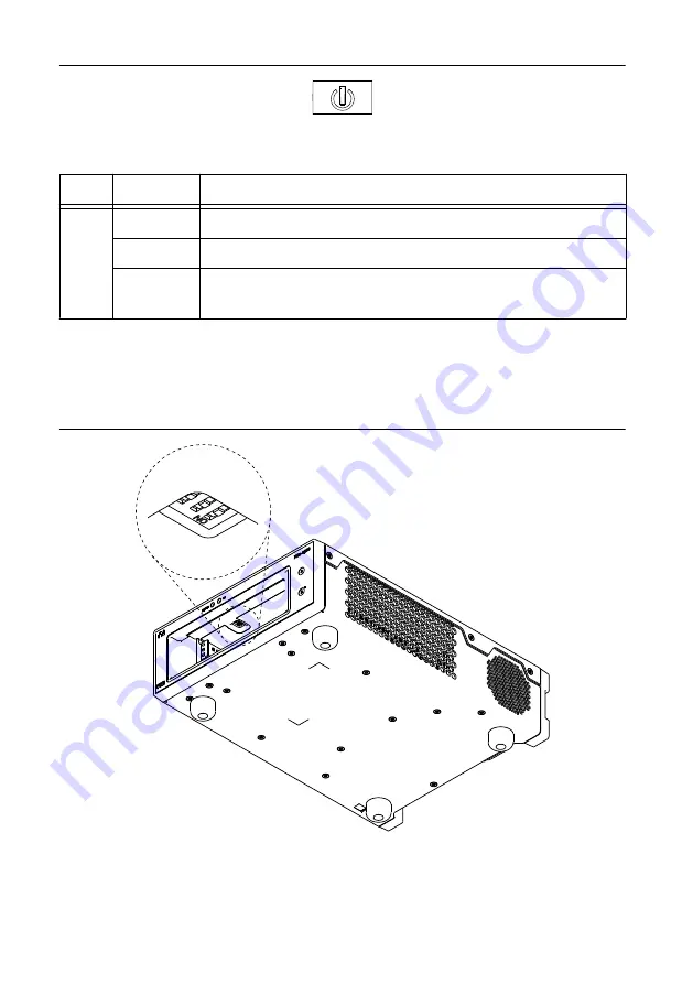
DIP Switches
Use the DIP switches to control chassis behavior. Refer to the following figure for the DIP
switches location.
Figure 10. PXIe-1090 Dip Switches Location
PXIe-1090 User Guide
|
© National Instruments Corporation
|
15