8
ACB Interlock
3. Remove ACB bodies from their carriages now and covered to avoid arc shoot contamination. Do
not insert ACB bodies until final testing stage.
Drill the cable interlock path holes in the switchboard.
Conduit or bushing should be used to give the cable a clear path. Sharp cut metal edges may damage the
cables! Cable route radius must not be less that 150mm.
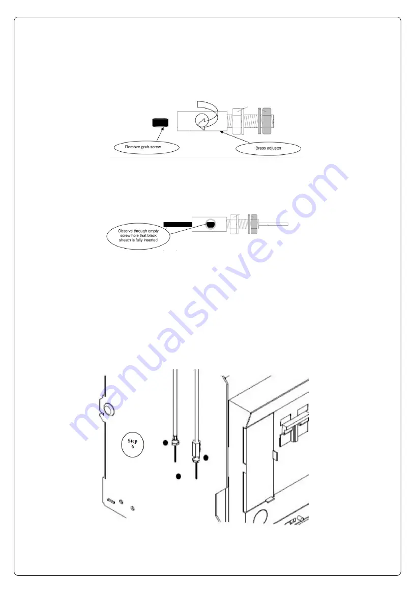
4. Remove the grub screw from the brass adjuster and ensure the nuts are as shown below:
5.
Insert the ‘
open
’ end of the cable into the brass adjuster. Observe through the grub screw hole that the
black outer sheath of the cable is fully pushed into the brass adapter. The inner core should protrude at
least 45mm from the ends of the black outer sheath on both ’open’ and ‘fixed’ cable ends (in other words
the total inner core length should be at least 90mm longer than black outer sheath total length after the
loose brass adjustment end is fitted).
6. Insert the grub screw with fingers until the screw meet the black outer sheath inside the brass adjuster. With
the allen key provided perform a further half to three quarter turn to secure the black outer sheath to the
brass adjuster. Check the integrity of the fixture by trying to pull the brass adjuster from the interlock cable.
Excessive force is not required, a firm pull is adequate. The grub screw MUST NOT be over
tightened. Doing so will restrict the movement of the inner core and compromise the interlock.
7. Install cables in the path made above in 3). Cables should be secured every 500mm if a continuous conduit
has not been used. Cable ends once installed should finish next to the bottom left hand side of each
carriage (as shown below). Ensure that an equal number of Cable ’open’ and ‘fixed ends’ are available at
each ACB in accordance with table 2.0.


