


3. Connect the red lead to the anode of the diode to be tested and the black lead to the cathode.
Read LCD display to get the forward voltage drop of the diode under testing.
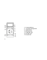
3.6 TESTING TRANSISTORS
1. Set the function switch at hFE position.
2. Identify whether the transistor NPN or PNP type and locate emitter, base and collector lead.
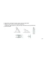
Insert Ieads of the transistor to be tested into proper holes of the testing socket on the front panel.
3. LCD display will show the approximate hFE value.
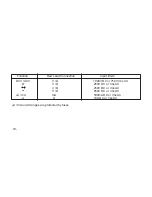
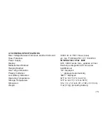
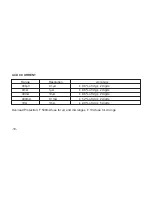
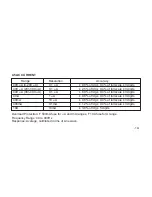
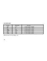
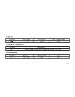
4. SPECIFICATIONS
Accuracy is specified for a period of one year after calibration and at 64°F to 82°F (18°C to 28°C)
with relative humidity to 80%.
-14-


