Nexus 21 XL-75s Скачать руководство пользователя страница 29

29 
 

Adjustments 


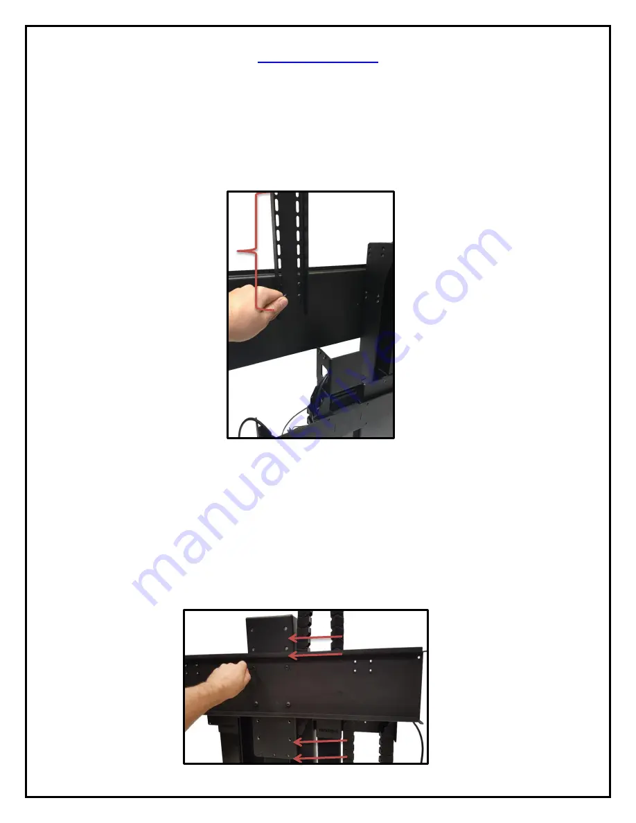
The Top Support Brackets bolt to the back of the Screen Back Plate and have slotted holes that allow you to adjust the 

installation height of the Lift in ¼” increments.   


Note: 

 You must use all four bolt holes on the Screen Back Plate when adjusting the Top Support Brackets.  


You can move the Screen Back Plate up and down, along the Screen Support to raise and lower the position of the TV on 
the lift. See photo to the left for reference.  


Note: 

If you lower the Screen Back Plate You will need to adjust the Top Support Brackets, so that they do not hit the 

Upper Cable Management Track. 


Содержание XL-75s

Страница 1: ...1 TV Lift System Model XL 75s Installation Instructions ...

Страница 2: ...y and installation please make sure that you have all items included on the list If any parts are missing or damaged please contact Nexus 21 Our contact information is shown at the top of this page Parts List Lower Lift Columns Upper Lift Column Screen Support Base Plate Upper Column Brace Center Riser Bracket Rear Support Bracket Screen Back Plate Lower Column Support Top Plates Lower Column Brac...

Страница 3: ...ne Screw 16 Twelve 12 6mm x 20mm Flat Head Machine Screw 17 Sixteen 16 6mm x 10mm Button Head Machine Screw 19 Eight 8 6mm x 12mm Button Head Machine Screw 20 Four 4 3 8 16 x Button Head Machine Screw 21 Two 2 Screen Locks In bag labeled PDM 0108 22 Four 2 1 x Steel Threaded Taper Pins For Floating Top 23 Two 2 10 x 1 Flat Head Wood Screw For Backup Switch 24 Thirty Six 36 10 x Truss Head Wood Scr...

Страница 4: ...hed 12 Keep all documentation 13 Heed all warnings 14 Clean only with a dry cloth 15 Refer all service questions to Nexus 21 if the system does not operate normally Nexus 21 disclaims any liability for modifications improper installations or installations over the specified weight range Nexus 21 will not be liable for any damages arising out of the use of or inability to use Nexus 21 products Nexu...

Страница 5: ...ur universal remote will learn the IR codes from the provided IR Handset which will enable you to control the lift The universal remote will then communicate with the eye located on the IR Receiver via your 3 rd party emitter or flasher Instructions for setting the TV Lift s travel limit are on Page 30 NOTE If you are NOT planning on using a 3rd party Universal Remote switch to the RF setup There ...

Страница 6: ...HT of the Lift will be a minimum of 45 8 up to a maximum of 53 8 with the Top Support Brackets in the highest position See installation dimensions diagram on following page About the Cabinet Lid Cabinet Top SAFETY NOTICE WARNING YOU MUST NOT DIRECTLY SCREW THE CABINET LID TOP TO THE LIFT SYSTEM THIS CREATES HAZARDOUS PINCH POINTS AND MAY AFFECT THE OPERATION OF THE LIFT OR CAUSE DAMAGE TO THE CABI...

Страница 7: ...ly ii Lower Support Assembly iii Installing the Lift Columns into your Cabinet iv Upper Actuation Assembly a Assembling the Actuation System b Assembling the Cable Management System c Assembling the TV Mounting System 2 Connecting the Lift 3 Mounting the TV to the Lift 4 Creating a Floating Lid a Threaded Tapered Pins b Lid Catches 5 Lift Adjustability Points 6 Dimensional Drawing 7 Reference Guid...

Страница 8: ...rew Small Hex Key Step 1 Attach 1 Base Plate to the Lower Lift Column using 2 6 x 10 mm BHMS screws Refer to picture 1 Step 2 Attached 1 Lower Column Supports to the Lower Lift Column using 2 6 x 10 BHMS screws Refer to picture 2 Step 3 Repeat steps 1 and 2 for the second column this time attaching the Base Plate to the alternate side Step 4 The Lower Actuation Assembly is now complete ...

Страница 9: ...Place the Lower Column Braces over the raised segments of the Rear Support Bracket to match picture 5 Step 6 Attach the 2 Lower Column Braces to the Rear Support Bracket using 8 6x 12 mm BHMS Screws Leave the outer screws slightly loose for adjustment in the steps for Assembling the Actuation System Refer to picture 6 Step 7 The Lower Support Bracket Assembly is now complete ...

Страница 10: ...racket Assembly 35 10 x THWS Screws Your Cabinet Phillips Drill Bit Drill Step 8 Place the Lower Support Bracket over the Lower Actuation System Ensure the Nexus 21 Logo is not upside down and the 90 degree bend is on the right hand side Step 9 Place the Lower Actuation System with the Lower Support Bracket into your cabinet 8 9 ...

Страница 11: ...t Columns Step 11 Center the Lift horizontally in your cabinet and mount the Lower Column Support and Base Plate for each column to the cabinet using 20 10 x THWS Screws Step 12 Repeat Step 10 if necessary and mount the Lower Support Bracket Assembly to the rear wall of the cabinet using 15 10 x THWS Screws 11 12 ...

Страница 12: ...Hex Key Step 13 Attach the Upper Lift Column to the Center Riser Bracket using 4 6 x 20 mm FHMS Screws Ensure that the pigtail cable for the Upper Lift Column is facing the interior of the Center Riser Bracket Refer to picture 13 Step 14 Attach the Upper Column Brace to the Center Riser Bracket using 2 6 x 12 mm FHMS Refer to picture 14 Step 15 The Upper Actuation Assembly is now complete ...

Страница 13: ...ort the Upper Actuation Assembly until you fasten it to the Lower Actuation Assembly See photo to the left for reference Step 17 Fasten the left side of the Upper Actuation Assembly to the Lower Actuation Assembly using 4 6 x 20 FHMS Screws See photo to the right for reference Step 18 Fasten the Center Riser Bracket to the Lower Actuation Assembly then place the Right Cable Management Bracket over...

Страница 14: ...pter Plate and attach the Swivel Adapter Plate to the top of the Center Lift Column using 4 6 x 12 BHMS Screws Step 20 Re Attach the Swivel Mechanism to the Swivel Adapter Plate and fasten them together by tightening the screws in the unthreaded holes on the top of the Swivel ...

Страница 15: ...ck Screen Support Actuation System 4 5 x 12 mm FHMS Screws 4 6 x 10 mm BHMS Screws 4 5m Motor Cable 6 Adapter Cable Small Hex Key 3 mm Hex Key Snakeskin Wrap Step 21 Attach the Cable Management Track to the Center Riser Bracket using 2 5 x 12mm FHMS Screws Step 22 Connect the 4 5m Motor Cable to the Center Lift Column ...

Страница 16: ...oth the Swivel Cable and 4 5m Motor Cable up through the Right Cable Management Bracket through the Slot in the Center Riser Bracket and down through the Cable Management Track Step 25 Feed both the Swivel Cable and 4 5m Motor Cable through the Cable Management Track until the cables rest equal to the Lower Support Brackets ...

Страница 17: ...Bracket with the threaded holes on the Swivel Mechanism and it using 4 6 x 10 BHMS Screws Step 27 Starting from the bottom of the Screen Support Bracket use the Snakeskin Wrap to wrap the Swivel Cable and 4 5m Motor Cable leaving the loop between the Lower Lift Columns ...

Страница 18: ... Cable Management Bracket to the right the pin the cables against the Center Riser Bracket and tighten the 2 6 x 20 FHMS Screws Step 29 Attach the right half of the Cable Management Track to the Rear Support Bracket using 2 5 x 12 mm FHMS Screws You have successfully installed the Cable Management System ...

Страница 19: ...ack Plate using the 4 holes towards the middle of the Screen Support for now as adjustments will be covered in the Adjustments section of the Instruction Manual on page 28 Step 31 Using the remaining 2 holes on the Screen Back Plate attach the Center Cable Management Bracket using 2 3 8 x 16 BHMS Screws Ensure the larger hole in the bracket is face down and to the left See photo to right for refer...

Страница 20: ...ting towards the front of the Lift System See photo to the left for reference Step 33 Attach both of the Top Plates to the top of the Top Support Brackets using 4 6 x 12 FHMS Screws Ensure that wings of the Top Plate are pointing towards the front of the Lift System See photo to the left for reference You have successfully installed the TV Mounting System ...

Страница 21: ...ing the Lift System Step 34 Using the XL 75s IR Wiring Diagram below connect the cables for your Lift System with IR Controls Note If you have RF Controls please see the next page for the XL 75s RF Wiring Diagram ...

Страница 22: ...22 Step 34 Continued Use this XL 75s RF Wiring Diagram if you have RF Controls Note If you have IR Controls refer to the previous page ...

Страница 23: ...P with raised dot and a DOWN 3 Press the DOWN button and HOLD IT DOWN for approximately 5 seconds 4 You should see a slight movement in the Lift Column If you do not see the movement release the Down button and repeat the process press and hold the Down button again for 5 seconds 5 Once you have seen the slight movement the Lift System is now functional 6 Test it by pressing the Up button no need ...

Страница 24: ...e TV 3 Using the four 4 Square Multi Mount washers and the TV mounting screws selected from the bag attach and tighten the hardware DO NOT OVERTIGTHEN HARDWARE DAMAGE TO TV MAY RESULT Diagram B installation procedure 1 Place the flat screen TV face down on a protected surface 2 Position the Vertical Mounting Bars equidistant from the bottom and top of the TV with the slots facing toward the top of...

Страница 25: ...reen Locks into both Vertical Mounting Bars Using 2 Screen Locks place one Screen Lock on the bottom set of hooks for each Vertical Mount Bar Using a Philips Head Screwdriver not provided tighten the Screen Locks against the bottom of the Screen Back Plate This will ensure the TV does not slide left to right and eliminate the TV from being lifted off of the mount ...

Страница 26: ... Plates are hand tight and centered before you mark your lid You may use the 2 outer holes or all 4 holes Step 42 Remove Cabinet Lid and drill two holes in the marked positions using a 7 32 drill bit deep in the underside of the Cabinet Lid Tip You can wrap tape around the bit deep to ensure you don t go too far into the lid Tip If you have a granite marble or quartz lid you can put a wood sub dec...

Страница 27: ...p This option assumes that you have cut out part of your cabinet top customizing it to the size of your TV That cut out lid then sits on the Top Plate of the Lift System held in place by the Taper Pins and raises lowers with the TV You must set up a catch for the Cut Out Lid so that when the TV lowers the Lid stops level with the rest of your cabinet top like a manhole cover and the Lift System co...

Страница 28: ...opening This will provide a support point for the lid to rest on while the lift is in the fully retracted position assuring the lid is flush with the rest of the cabinetry every time There are multiple ways to properly create a catch for the lid to rest on when the lift is in the fully retracted position Here are a few other examples on how to create a catch or lip for the cabinet lid to rest upon...

Страница 29: ...use all four bolt holes on the Screen Back Plate when adjusting the Top Support Brackets You can move the Screen Back Plate up and down along the Screen Support to raise and lower the position of the TV on the lift See photo to the left for reference Note If you lower the Screen Back Plate You will need to adjust the Top Support Brackets so that they do not hit the Upper Cable Management Track ...

Страница 30: ...30 ...

Страница 31: ...setting the Lift from Safe Mode Safe Mode occurs when power is lost while the lift is extended 1 The lift will only retract and it moves at half the speed 2 Press and hold the down button until the lift fully retracts 3 Then follow the steps to Reinitialize the lift Pairing your RF Remote 1 Locate the pinhole on the side of the RF Receiver 2 Using a paper clip press and hold the button inside the ...

Страница 32: ...32 Connecting the Lift to your Home Control System ...

Страница 33: ...33 Intentionally Left Blank ...

Страница 34: ...34 Intentionally Left Blank ...

Страница 35: ...35 Intentionally Left Blank ...

Страница 36: ...36 866 500 5438 ...

Отзывы: