

NPST961 Series Instruction Manual
NPST961 Series V3.0
www.nextys.com
Page 3/5
USER INSTRUCTIONS
1) Description:
DIN rail mountable primary switched-mode power supply with 340...550Vac (520…725Vdc) suitable for Three Phases main line and DC line.
2) Installation:
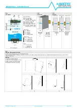
use DIN-rails according to EN60715. Installation should be made vertically (see Fig.4). For better device stability fix the rail to the wall close to the point where
the device is to be mounted. In order to guarantee sufficient convection, we recommend observing a minimum distance to other modules (see Fig.3).
The device is provided with a thermal protection; a limited air flow can cause the thermal protection tripping.
The SMPS automatically restarts after cooling. To get normal operation reduce the temperature of the air surrounding the power supply, increase the ventilation or reduce the
load (see Fig.8)
3) Connections
: the device is equipped with pluggable screw terminals. To avoid sparks, do not connect or disconnect the connectors before having previously turned-off input
power and waited for internal capacitors discharge (minimum 1 minute)
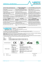
In order to comply with UL certification, use appropriate copper cables of indicated cross section, designed for an operating temperatures of:
60°C for ambient up to 45°C
75°C for ambient up to 60°C
90°C for ambient up to 70°C
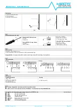
Strip the connecting ends of the wires according to the indication and ensure that all strands of a stranded wire enter the terminal connection (see Fig.5)
4) Input protection:
the device input is provided with varistors against overvoltage. Input is not provided with internal fuses, thus an external short circuit/overcurrent protection
must be provided by the end user (see Fig.6).
For operation on a three phases system, a protection fuse on each phase must be provided.
Surge protection:
it is strongly recommended to provide external surge arresters (SPD) according to local regulations.
5) AC input connection:
the device can be connected to three phases AC lines with Uin 400…500Vac (see Fig.7). Please connect first the PE.
6) DC input connection:
connect L1 terminal to (+) positive pole, L2 terminal to (-) negative pole, L3 do not connected and
I
terminal to GND. Rated voltage 520...725Vdc.
The device is also suitable for photovoltaic or wind turbine applications (see Fig.7).
7) Output connection:
The device is suitable for
SELV
and
PELV
circuitry. Pay attention NPST961-72 is not
SELV
.
Uout can be adjusted with a potentiometer to a wide range (see Fig.1)
Check Uout before connecting the power supply to the load. With output voltage set to the max. value, the continuous [current x voltage] must not exceed the nominal power.
8) Parallel connection and redundancy:
power supplies can be connected in parallel to increase power. For paralleling for power set the Ilim jumper to C.C. algorithm.
Uout must be set uniformly (±100mV) on each power supply and the wiring must be symmetrical to ensure an equal current distribution.
For redundant connection, use an external isolating device must be used (see accessory device).
9) Output protection:
the device is protected against overload (OL) / short circuit (SC) / overvoltage (OV) / overtemperature (OT).
OL and SC:
are controlled by a hiccup mode or a constant current (C.C.) mode protection with the following behaviour.
The Hiccup mode or C.C. mode are selectable with Jumper (see Fig.1)
OL behaviour in hiccup mode:
max. OL = 1.5 x In the output voltage remains constant at nominal voltage for about 5s and after that time the device starts an ON/OFF cycle.
OL behaviour in CC mode:
max. OL = 1.5 x In the output voltage remains constant at nominal voltage for about 5s and after that time the device limits the current at In. If the
load resistance is further decreased the output voltage starts to drop. The device never switches OFF.
SC behaviour in hiccup mode:
the device supplies 1.5 x In for about 5s and after that time the device starts an ON/OFF cycle.
SC behaviour in CC mode:
the device supplies 1.5 x In and the output voltage drops to a level depending on the impedance of the failed load circuit. After 5s the current is
limited to In. The device never switches OFF.
Output OV circuit protection:
the output is protected against potential OV due to internal malfunction or coming from the load for Uout
Unom x 1.2…1.4, depending on the
model.
OT protection:
turns off the device if the internal temperature exceeds a safe limit.
The device restarts automatically after cooling down. To recover to normal operation reduce air temperature surrounding the power supply, increase cooling or reduce load
(see Fig.8).
10) Feeding DC motors:
it is possible to feed DC motors considering that when a motor starts-up under effort its consumption is much higher than the nominal current and it
can trigger overcurrent protection (see accessory device). For these applications the C.C. (Constant Current) mode of current limitation is recommended.
NOTE:
motors can generate high conducted noise on the DC line. Therefore it is not recommended to feed on the same line motors and equipment sensitive to noise.
11) Operation with Battery:
when a battery is connected in parallel to the Output for backup purposes; the NPST961 must be set on C.C. mode to avoid battery over-charging
(see accessory device).


