


NPS2400
User’s Manual
Rev. 3.0
– 17.02.2015
Page 12/38
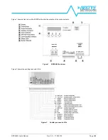
4.3.4
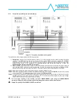
Connection in parallel (power and redundancy)
Figure 10 Connection of multiple units in parallel
The parallel connection may have
one
of the following purposes:
1)
Redundancy
: several units (unlimited number in theory, 2...4 units in practice) can be used to increase the system
reliability. If one SMPS fails the load will be still powered from another SMPS connected in parallel. The NPS2400
integrates an active ORing diode so that several units can be directly connected in parallel without the need for an
external ORing module. In this configuration the
maximum power sunk by the load must be < Pnom
.
The
SHARE+/SHARE- signals should NOT be connected.
2)
Power increase
: this configuration is used to increase the system power capacity by summing the output current of
each individual SMPS connected in parallel to the load. To obtain the system’s best performance SHARE+/SHARE-
signals must be daisy chain connected on all SMPS’. This allows equal current sharing between all the SMPS’.
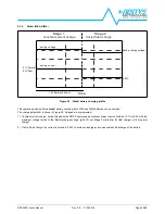
Note 1:
When used in parallel for power increase the maximum number of SMPS is 4 units.
Note 2:
When used in parallel for power increase the maximum total output current will be
0.9*Iout*N
, where N is the number
of connected SMPS’. The
maximum power
is thus limited to
0.9*N*Pnom<8.7kW
.
Note 3:
To achieve the best power sharing between the parallel connected devices the output voltage of each device must be
adjusted at the same value with a tolerance of maximum 0.2V. The share bus will then slightly vary the output voltage
of each SMPS to achieve the best possible power sharing.
Do not connect anything to the auxiliary connector SENSE+/SENSE- when using the SHARE+/SHARE-
connection! Wrong connection to these signals may damage the devices and the connected load.
Respect the polarity of the SHARE+/SHARE- connections!


