Nexcom NDIS M537 Скачать руководство пользователя страница 35

Copyright © 2018 NEXCOM International Co., Ltd. All Rights Reserved.

21

NDiS M537 User Manual 

Chapter 3: System Setup

Installing the CPU (Socket Type)

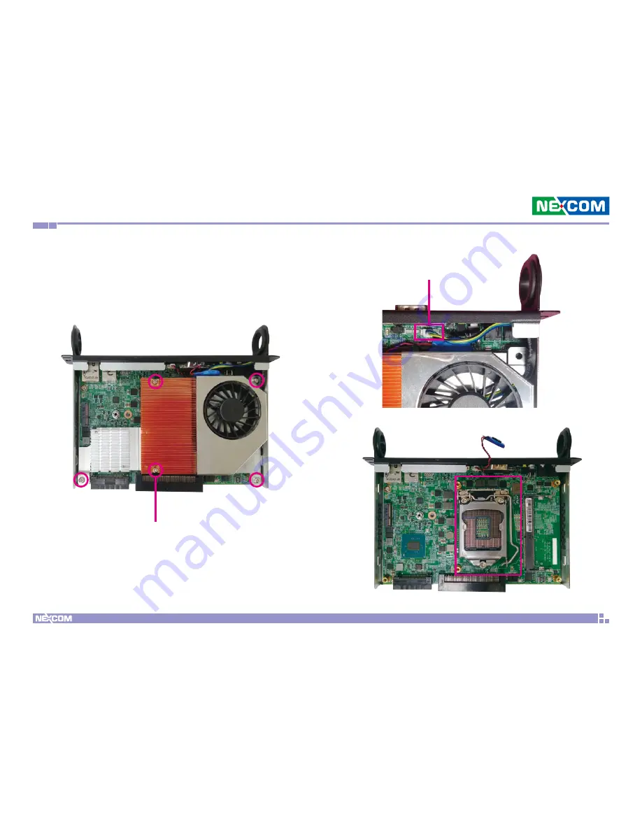
1. Remove the chassis cover, then loosen all the five screws and unplug the 

fan power connector to remove the cooler and access the CPU socket. 

Fan Power Connector

Screw

Содержание NDIS M537

Страница 1: ...NEXCOM International Co Ltd NEXCOM International Co Ltd Published September 2018 www nexcom com Intelligent Platform Services Business Unit Digital Signage Platform NDiS M537 User Manual ...

Страница 2: ...duction Overview 1 Key Features 1 Physical Features 2 Front Panel 2 Rear Panel 2 Hardware Specifications 3 Mechanical Dimensions 4 Chapter 2 Jumpers and Connectors Before You Begin 5 Precautions 5 Locations of the Jumpers and Connectors for NDiB M537 6 Top View 6 Bottom View 7 Jumper Settings 8 Jumpers 9 RTC Clear Jump 9 Connector Pin Definitions 10 External I O Interfaces 10 Power Switch 10 Syste...

Страница 3: ...t Type 21 Installing a SO DIMM Memory Module 25 Installing an M 2 SSD Storage Module 28 Installing a Wireless LAN Module 30 Chapter 4 BIOS Setup About BIOS Setup 33 When to Configure the BIOS 33 Default Configuration 34 Entering Setup 34 Legends 34 BIOS Setup Utility 36 Main 36 Advanced 37 Chipset 45 Security 46 Boot 46 Save Exit 47 Appendix A Watchdog Programming Guide 48 ...

Страница 4: ...NEXCOM International Co Ltd All other product names mentioned herein are registered trademarks of their respective owners Regulatory Compliance Statements This section provides the FCC compliance statement for Class A devices and describes how to keep the system CE compliant Declaration of Conformity FCC This equipment has been tested and verified to comply with the limits for a Class A digital de...

Страница 5: ...nd Polybrominated diphenyl Ethers PBDE 0 1 or 1 000ppm In order to meet the RoHS compliant directives NEXCOM has established an engineering and manufacturing task force to implement the introduction of green products The task force will ensure that we follow the standard NEXCOM development procedure and that all the new RoHS components and new manufacturing processes maintain the highest industry ...

Страница 6: ...fective products making sure it is durable enough to be resistant against further damage and deterioration during transportation In case of damages occurred during transportation the repair is treated as Out of Warranty Any products returned by NEXCOM to other locations besides the customers site will bear an extra charge and will be billed to the customer Repair Service Charges for Out of Warrant...

Страница 7: ...and power supply are inconsistent with these instructions or the instructions for accessory modules contact the supplier to find out how you can ensure that your computer meets safety and regulatory requirements Cautions Electrostatic discharge ESD can damage system components Do the described procedures only at an ESD workstation If no such station is available you can provide some ESD protection...

Страница 8: ...e the soft metal or plastic parts of the connectors Safety Information Before installing and using the device note the following precautions Read all instructions carefully Do not place the unit on an unstable surface cart or stand Follow all warnings and cautions in this manual When replacing parts ensure that your service technician uses parts specified by the manufacturer Avoid using the system...

Страница 9: ...he voltage and current rating marked on the product 10 All cautions and warnings on the equipment should be noted 11 If the equipment is not used for a long time disconnect it from the power source to avoid damage by transient overvoltage 12 Never pour any liquid into an opening This may cause fire or electrical shock 13 Never open the equipment For safety reasons the equipment should be opened on...

Страница 10: ...ion of the installed software operating system version application software etc A complete description of the problem The exact wordings of the error messages Warning 1 Handling the unit carry the unit with both hands and handle it with care 2 Maintenance to keep the unit clean use only approved cleaning products or clean with a dry cloth Conventions Used in this Manual Warning Information about c...

Страница 11: ... 920 Chung Cheng Rd ZhongHe District New Taipei City 23586 Taiwan R O C Tel 886 2 8226 7796 Fax 886 2 8226 7792 Email sales nexcom com tw www nexcom com tw NEXCOM Intelligent Systems Taichung Office 16F No 250 Sec 2 Chongde Rd Beitun Dist Taichung City 406 R O C Tel 886 4 2249 1179 Fax 886 4 2249 1172 Email sales nexcom com tw www nexcom com tw Japan NEXCOM Japan 9F Tamachi Hara Bldg 4 11 5 Shiba ...

Страница 12: ...w nexcomitalia it NEXCOM Shanghai Room 603 604 Huiyinmingzun Plaza Bldg 1 No 609 Yunlin East Rd Shanghai 200333 China Tel 86 21 5278 5868 Fax 86 21 3251 6358 Email sales nexcom cn www nexcom cn NEXCOM Surveillance Technology Corp Room202 Building B the GuangMing Industrial Zone Zhonghua Rd Minzhi Street Longhua District Shenzhen 518131 China Tel 86 755 8364 7768 Fax 86 755 8364 7738 Email steveyan...

Страница 13: ...ollowing table Item Part Number Name Description Qty 1 50311F0111X00 Flat Head Screw Long Fei F3x5ISO Nylok Black F3x5 Black Nylok 2 2 5060200082X00 Thermal Pad NDiS B533 VER A EAPUS 25x25x0 2mm 2 3 5060200187X00 Thermal Pad for G100 VER A S W 10x10x1mm K 3w mk 2 4 6013300521X00 NDiS M533 Cable kit EPE VER A SENTENEL 230x200x15mm 1 5 6013300709X00 EPE FOR NDiS M335 VER A SENTENEL 227x200x75mm 1 6 ...

Страница 14: ...ll Rights Reserved xiv NDiS M537 User Manual Preface Ordering Information The following below provides ordering information for NDiS M537 NDiS M537 P N 10W00M53700X0 7th 6th generation Intel Core LGA1151 type processor OPS PLUS Intel Q170 chipset ...

Страница 15: ...l Core processors Following open pluggable standard NDiS M537 can perfectly fit into a myriad of OPS PLUS panels and is compact in size Yet NDiS M537 has high scalability allowing for easy storage capacity expansion through pluggable M 2 storage unit and effortless functional extension through FX18 60P PCIe x4 DP1 2 expansion modules Changing system memory is also made simple In addition NDiS M537...

Страница 16: ...hts Reserved 2 NDiS M537 User Manual Chapter 1 Product Introduction Physical Features Front Panel Rear Panel Antenna Hole Antenna Hole Mic in Storage LED Power Button Reset Button JAE TX25 80Pin Line out COM LAN Mini DisplayPort USB 3 0 HRS FX18 60Pin ...

Страница 17: ...holes 1 x Mic in phone jack 1 x Line out phone jack 1 x DB9 for RS232 COM3 I O Interface Rear TX25 1 x TMDS HDMI 2 0 1 x USB 3 0 2 x USB 2 0 1 x UART 3 3V TTL COM2 1 x Audio out L R DC input 12V 19V Control signals PWR_STATUS PS_ON PB_DET CEC SYS_FAN I O Interface Rear FX18 1 x GPIO signal 2 x I2C signal LAN managements signals 1 x DP1 2 signal PCIe x4 signal Storage Device 1 x M 2 2242 SATA signa...

Страница 18: ...ht 2018 NEXCOM International Co Ltd All Rights Reserved 4 NDiS M537 User Manual Chapter 1 Product Introduction Mechanical Dimensions 30 0 40 200 0 40 4 5 5 23 3 192 118 0 40 1 1 27 4 180 0 40 149 8 6 13 25 68 ...

Страница 19: ...urself before touching any internal components by touching a metal object Static electricity can damage many of the electronic components Humid environments tend to have less static electricity than dry environments A grounding strap is warranted whenever danger of static electricity exists Precautions Computer components and electronic circuit boards can be damaged by discharges of static electri...

Страница 20: ...s and Connectors The figure below is the top and bottom view of the NDiB M537 mainboard which is the mainboard used in NDiS M537 It shows the locations of the jumpers and connectors J5 CN7 USB1 CON1 CN3 CN2 CN1 J4 JP1 J2 SW1 SW2 CN4 CN5 LED1 Top View Locations of the Jumpers and Connectors for NDiB M537 ...

Страница 21: ...Copyright 2018 NEXCOM International Co Ltd All Rights Reserved 7 NDiS M537 User Manual Chapter 2 Jumpers and Connectors CN6 Bottom View ...

Страница 22: ...e jumpers ensure that the jumper caps are placed on the correct pins When the jumper cap is placed on both pins the jumper is short If you remove the jumper cap or place the jumper cap on just one pin the jumper is open Refer to the illustrations below for examples of what the 2 pin and 3 pin jumpers look like when they are short on and open off Two Pin Jumpers Open Left and Short Right Three Pin ...

Страница 23: ...d All Rights Reserved 9 NDiS M537 User Manual Chapter 2 Jumpers and Connectors Jumpers RTC Clear Jump Connector type 1x3 3 pin header 2 54mm pitch MALE 180D Connector location JP1 Pin Settings 1 2 On Normal 2 3 On Clear CMOS 1 2 On default 1 3 ...

Страница 24: ...rved 10 NDiS M537 User Manual Chapter 2 Jumpers and Connectors Connector Pin Definitions External I O Interfaces Power Switch Connector location SW1 Power LED Definition ON Blue OFF Red System Reset Switch Connector location SW2 Pin Definition 1 2 System Reset ...

Страница 25: ...tor location USB1 Pin Definition Pin Definition 1 TCT 2 TD4 3 TD4 4 TD3 5 TD3 6 TD2 7 TD2 8 TD1 9 TD1 10 TCTG 11 Left_LED 12 Left_LED 13 Right_LED 14 Right_LED Left LED Link Active Green Right LED 1G 100 Green Orange 1 8 Pin Definition Pin Definition 1 VCC 2 USB0_N 3 USB0_P 4 GND 5 USB3_RX0_N 6 USB3_RX0_P 7 GND 8 USB3_TX0_N 9 USB3_TX0_P 10 VCC 11 USB1_N 12 USB1_P 13 GND 14 USB3_RX1_N 15 USB3_RX1_P...

Страница 26: ...ni DisplayPort Connector location CN7 Pin Definition Pin Definition 1 PWR_IN 2 HPD_GND 3 TBT_HD2CA_0 4 TBT_CA2HD_0 5 TBT_HD2CA_0 6 TBT_CA2HD_0 7 GND1 8 GND2 9 LSTX 10 RESERVED1 11 LSRX 12 RESERVED2 13 GND3 14 GND4 15 TBT_HD2CA_1 16 TBT_CA2HD_1 17 TBT_HD2CA_1 18 TBT_CA2HD_1 19 RETURN 20 PWR_OUT 2 1 19 20 LED Connector location LED1 LED LED Definition HDD Yellow HDD ...

Страница 27: ...mpers and Connectors Mic in Connector Connector type 3 5mm TRS Connector location CN4 Pin Definition Pin Definition 1 IN OUT_R 2 JD 3 GND 4 IN OUT_L 5 GND 6 GND Line out Connector Connector type 3 5mm TRS Connector location CN5 Pin Definition Pin Definition 1 IN OUT_R 2 JD 3 GND 4 IN OUT_L 5 GND 6 GND ...

Страница 28: ... GND 29 HDMI0_SDA 13 DDP_AUXN 30 HDMI0_SCL 14 DDP_AUXP 31 HDMI0_HPD 15 DDP_HPD 32 GND 16 GND 33 VIN_M 17 HDMI0_CLK_N 34 VIN_M Pin Definition Pin Definition 35 VIN_M 58 USB_TX2P 36 VIN_M 59 GND 37 VIN_M 60 USB_DN2 38 VIN_M 61 USB_DP2 39 VIN_M 62 GND 40 VIN_M 63 USB_DN7 41 NC 64 USB_DP7 42 NC 65 GND 43 NC 66 USB_DN6 44 NC 67 USB_DP6 45 NC 68 GND 46 NC 69 SKPR_LOUT 44 47 NC 70 SKPR_ROUT 44 48 NC 71 H...

Страница 29: ...NX 9 PCIE RXN2 24 DDP1_AUNP 10 PCIE RXP2 25 GND 11 GND 26 DDP1_1N 12 GND 27 DDP1_1P 13 PCIE RXN3 28 GND 14 PCIE RXP3 29 DDP1_0N 15 GND 30 DDP1_0P MH1 GND MH3 NC MH2 GND MH4 NC Pin Definition Pin Definition 31 PCIE_WAKE 46 PCIE TXP3 32 GND 47 GND 33 PCIE TXN0 48 I2C_CLK_LAN 34 PCIE TXP0 49 I2C_DATA_LAN 35 GND 50 LAN_DISABLE 36 GND 51 SLEEP_S3 37 PCIE TXN1 52 PICe_RST 38 PCIE TXP1 53 GPIO 39 GND 54 ...

Страница 30: ...Chapter 2 Jumpers and Connectors Pin Definition 1 GND 2 3V Internal Connectors RTC Battery Connector Connector type 1x2 2 pin header Connector location J4 Fan Connector Connector type 1x4 4 pin header Connector location J2 Pin Definition Pin Definition 1 GND 2 VCC 3 SPEED 4 CONTROL 1 2 1 4 ...

Страница 31: ...17 NDiS M537 User Manual Chapter 2 Jumpers and Connectors Debug 80 Port Connector Connector type 1x10 10 pin header Connector location J5 Pin Definition Pin Definition 1 GND 2 PCIRST 3 33M_CLK 4 LPC_FRAME 5 LPC_AD3 6 LPC_AD2 7 LPC_AD1 8 LPC_AD0 9 3 3V 10 3 3V 1 10 ...

Страница 32: ...TA 18 GND 21 SOIO_WAKE 20 WAKE 23 SOIO_RESET 22 RXD HW Latch 33 GND 32 TXD 35 PETp0 34 CRS 37 PETn0 36 RTS 39 GND 38 VENDOR 41 PERp0 40 VENDOR Pin Definition Pin Definition 43 PERn0 42 VENDOR 45 GND 44 COEX 47 REFCLKp0 46 COEX 49 REFCLKn0 48 COEX 51 GND 50 SUSCLK 53 CLKREQ0 52 PERST 55 PEWAKE0 54 W_DISABLE 57 GND 56 W_DISABLE 59 PETp1 58 I2C_DATA 61 PETn1 60 I2C_CLK 63 GND 62 ALERT 65 PERp1 64 RES...

Страница 33: ...14 3 3V_7 15 GND4 16 3 3V_8 17 PERN2 18 3 3V_9 19 PERP2 20 NC2 21 GND5 22 NC3 23 PETN2 24 NC4 25 PETP2 26 NC5 27 GND6 28 NC6 29 PERN1 30 NC7 31 PERP1 32 NC8 33 GND7 34 NC9 35 PETN1 36 NC10 Pin Definition Pin Definition 37 PETP1 38 DEVSLP 39 GND8 40 NC11 41 PERN0 42 NC12 43 PERP0 44 NC13 45 GND9 46 NC14 47 PETN0 48 NC15 49 PETP0 50 PERST 51 GND10 52 CLKREQ 53 REFCLKN 54 PEWAKE 55 REFCLKP 56 NC16 57...

Страница 34: ... chassis cover make sure the unit s power is off and disconnected from the power sources to prevent electric shock or system damage CAUTION CAUTION CAUTION 1 The screws on the back are used to secure the cover to the chassis Remove these screws and put them in a safe place for later use 2 With the screws removed push back the cover and remove it from the chassis Screws on the back ...

Страница 35: ... Reserved 21 NDiS M537 User Manual Chapter 3 System Setup Installing the CPU Socket Type 1 Remove the chassis cover then loosen all the five screws and unplug the fan power connector to remove the cooler and access the CPU socket Fan Power Connector Screw ...

Страница 36: ...n lift the load lever up 3 Insert the CPU into the socket The triangular edge on the CPU must align with the corner of the CPU socket shown on the photo The CPU s notch will at the same time fit into the socket s alignment key Alignment key Alignment key Handle the CPU by its edges and avoid touching the pins The CPU will fit in only one orientation and can easily be inserted without exerting any ...

Страница 37: ...the retention tab Do not force the CPU into the socket Forcing the CPU into the socket may bend the pins and damage the CPU CAUTION CAUTION CAUTION 5 Remove the adhesive film on the thermal pad and place it onto the CPU CAUTION CAUTION CAUTION Please install the thermal pad and make sure the adhesive film on the thermal pad is removed before placing it on the heat sink ...

Страница 38: ...EXCOM International Co Ltd All Rights Reserved 24 NDiS M537 User Manual Chapter 3 System Setup 6 Put the cooler back to its original location and apply all the five screws and fan power connector to secure it in place ...

Страница 39: ...over and cooler removed install a memory module in the SO DIMM socket DIMM2 2 Push the ejector tabs which are at the ends of the socket outward This indicates that the socket is unlocked Note how the module is keyed to the socket Grasping the module by its edges align the module with the socket so that the notch on the module is aligned with the key on the socket The key ensures the module can be ...

Страница 40: ...ach end of the module until it slips down into the socket The contact fingers on the edge of the module will almost completely disappear inside the socket The ejector tabs at the ends of the socket will automatically snap into the locked position to hold the module in place 4 At the bottom of the system loosen the screws on the bottom cover then remove the cover from the chassis to install another...

Страница 41: ...Copyright 2018 NEXCOM International Co Ltd All Rights Reserved 27 NDiS M537 User Manual Chapter 3 System Setup 5 Follow the instructions in step 2 and step 3 above to install the memory module DIMM1 ...

Страница 42: ...ter 3 System Setup Installing an M 2 SSD Storage Module The system is equipped with an M 2 M Key connector To install an M 2 SSD module please follow the instructions below 1 At the bottom of the system loosen the screws on the bottom cover then remove the cover from the chassis M 2 M Key Slot ...

Страница 43: ...Chapter 3 System Setup 2 Insert the M 2 SSD module into the M 2 slot at a 45 degree angle until the gold plated connector on the edge of the module completely disappears inside the slot 3 With the module fully inserted tighten a screw into the mounting hole on the module to secure it Screw ...

Страница 44: ...module into the M 2 E key slot at a 45 degree angle until the gold plated connector on the edge of the module completely disappears inside the slot 1 With the chassis cover removed locate the M 2 E key slot on the mainboard M 2 E Key Slot The system is equipped with an M 2 E Key connector To install an M 2 Wireless LAN module please follow the instructions below ...

Страница 45: ...S M537 User Manual Chapter 3 System Setup 3 With the module fully inserted tighten a screw into the mounting hole on the module to secure it RF Cable Screw 4 Attach the RF cables onto the Wi Fi module and insert the antenna jack end of the cable through the antenna hole ...

Страница 46: ...ational Co Ltd All Rights Reserved 32 NDiS M537 User Manual Chapter 3 System Setup Ring2 Ring1 5 Insert the 2 rings ring 1 then ring 2 into the Wi Fi antenna jacks 6 Connect the external antennas to the Wi Fi antenna jacks Antenna ...

Страница 47: ...is configured with the values found in CMOS With easy to use pull down menus you can configure such items as Hard drives diskette drives and peripherals Video display type and display options Password protection from unauthorized use Power management features The settings made in the setup program affect how the computer performs It is important therefore first to try to understand all the setup o...

Страница 48: ...l be reported in one of two different ways If the error occurs before the display device is initialized a series of beeps will be transmitted If the error occurs after the display device is initialized the screen will display the error message Powering on the computer and immediately pressing Del allows you to enter Setup Press the key to enter Setup Legends Key Function Moves the highlight left o...

Страница 49: ...tup screen it indicates that there are more available fields not shown on the screen Use the up and down arrow keys to scroll through all the available fields Submenu When appears on the left of a particular field it indicates that a submenu which contains additional options are available for that field To display the submenu move the highlight to that field and press ...

Страница 50: ...H H Q170 D1 Unsupported Production 11 6 0 1126 Corporate SKU Mon 10 01 2018 08 43 48 System Date The date format is day month date year Day displays a day from Monday to Sunday Month displays the month from January to December Date displays the date from 1 to 31 Year displays the year from 1999 to 2099 System Time The time format is hour minute second The time is based on the 24 hour military time...

Страница 51: ...ion is used to view CPU status and configure CPU parameters Intel VMX Virtualization Technology When this field is set to Enabled the VMM can utilize the additional hardware capabilities provided by Vanderpool Technology Active Processor Cores Select the number of cores to enable in each processor package Intel SpeedStepTM Enables or disables Intel SpeedStep CPU C States Enables or disables CPU C ...

Страница 52: ...nfiguration SATA Mode Selection SATA Test Mode Serial ATA Port 0 Software Preserve Port 0 Hot Plug AHCI Disabled Empty Unknown Enabled Disabled SATA and RST Configuration This section is used to configure the SATA device option settings SATA Mode Selection Configures the SATA as AHCI mode AHCI This option configures the Serial ATA drives to use AHCI Advanced Host Controller Interface AHCI allows t...

Страница 53: ...Select Change Opt F1 General Help F2 Previous Values F3 Optimized Defaults F4 Save Exit ESC Exit Trusted Computing This section is used to configure Trusted Platform Module TPM settings Advanced Version 2 18 1263 Copyright C 2018 American Megatrends Inc Aptio Setup Utility Copyright C 2018 American Megatrends Inc Select Screen Select Item Enter Select Change Opt F1 General Help F2 Previous Values ...

Страница 54: ...o RAM Enable Hibernation Enables or disables system ability to hibernate OS S4 Sleep State This option may not be effective with some operating systems ACPI Sleep State Select the highest ACPI sleep state the system will enter when the suspend button is pressed The options are Suspend Disabled and S3 Suspend to RAM NCT6106D Super IO Configuration This section is used to configure the front and rea...

Страница 55: ...rsion 2 18 1263 Copyright C 2018 American Megatrends Inc Aptio Setup Utility Copyright C 2018 American Megatrends Inc Select Screen Select Item Enter Select Change Opt F1 General Help F2 Previous Values F3 Optimized Defaults F4 Save Exit ESC Exit Enable or Disable Serial Port COM REAR COM Configuration Serial Port Device Settings Change Settings Enabled IO 2F8h IRQ 3 IO 2F8h IRQ 3 Advanced Version...

Страница 56: ...em Fan Mode VCORE VCC5 VCC3 Disabled 62 ºc 4115 RPM Enable 0 872 V 5 100 V 3 312 V S5 RTC Wake Settings This section is used to configure system to wake from S5 using RTC alarm Exit Advanced Chipset PCIPnP Security Main Version 2 18 1263 Copyright C 2018 American Megatrends Inc Aptio Setup Utility Copyright C 2018 American Megatrends Inc Select Screen Select Item Enter Select Change Opt F1 General...

Страница 57: ...FI only Do not launch UEFI Advanced Boot Security Save Exit Main Version 2 18 1263 Copyright C 2018 American Megatrends Inc Aptio Setup Utility Copyright C 2018 American Megatrends Inc Select Screen Select Item Enter Select Change Opt F1 General Help F2 Previous Values F3 Optimized Defaults F4 Save Exit ESC Exit NVMe controller and Drive information No NVME Device Found CSM Configuration This sect...

Страница 58: ...rt if no USB devices are connected DISABLE option will keep USB devices available only for EFI applications USB Configuration USB Module Version USB Controllers 1 XHCI USB Devices 1 Keyboard Legacy USB Support XHCI Hand off 16 Enabled Disabled Legacy USB Support Enabled Enables Legacy USB Auto Disables support for Legacy when no USB devices are connected Disabled Keeps USB devices available only f...

Страница 59: ... Screen Select Item Enter Select Change Opt F1 General Help F2 Previous Values F3 Optimized Defaults F4 Save Exit ESC Exit System Agent SA Parameters System Agent SA Configuration System Agent SA Configuration This section is used to configure the System Agent SA configuration Chipset Version 2 18 1263 Copyright C 2018 American Megatrends Inc Aptio Setup Utility Copyright C 2018 American Megatrend...

Страница 60: ...d User Password Administrator Password Select this to reconfigure the administrator s password User Password Select this to reconfigure the user s password Boot Bootup NumLock State This allows you to determine the default state of the numeric keypad By default the system boots up with NumLock on wherein the function of the numeric keypad is the number keys When set to Off the function of the nume...

Страница 61: ... To save the changes and restart the system select this field then press Enter A dialog box will appear Confirm by selecting Yes You can also press F4 to save and exit Setup Discard Changes and Reset To exit the Setup utility without saving the changes and restart the system select this field then press Enter You may be prompted to confirm again before exiting You can also press ESC to exit withou...

Страница 62: ...s system reliability in industrial standalone or unmanned environments define SUPERIO_PORT 0x2E define WDT_SET 0xF0 define WDT_VALUE 0xF1 void main void Enter SuperIO Configuration outportb SUPERIO_PORT 0x87 outportb SUPERIO_PORT 0x87 Set LDN outportb SUPERIO_PORT 0x07 outportb SUPERIO_PORT 1 0x08 Set WDT setting outportb SUPERIO_PORT WDT_SET outportb SUPERIO_PORT 1 0x00 Use the second Use the min...

Отзывы: