


Copyright © 2012 NEXCOM International Co., Ltd. All Rights Reserved.
14
NDiS M532 User Manual
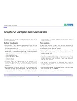
Chapter 2: Jumpers and Connectors
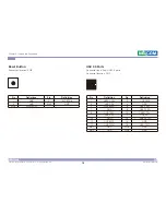
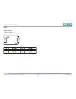
JAE-TX25
Connector location: CON1
Pin
Definition
Pin
Definition
1
DDP_3N
18
HDMI0_CLK_P
2
DDP_3P
19
GND
3
GND
20
HDMI0_TX0N
4
DDP_2N
21
HDMI0_TX0P
5
DDP_2P
22
GND
6
GND
23
HDMI0_TX1N
7
DDP_1N
24
HDMI0_TX1P
8
DDP_1P
25
GND
9
GND
26
HDMI0_TX2N
10
DDP_0N
27
HDMI0_TX2P
11
DDP_0P
28
GND
12
GND
29
HDMI0_SDA
13
DDP_AUXN
30
HDMI0_SCL
14
DDP_AUXP
31
HDMI0_HPD
15
DDP_HPD
32
GND
16
GND
33
VIN_M
17
HDMI0_CLK_N
34
VIN_M
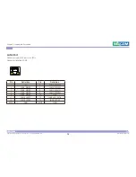
Pin
Definition
Pin
Definition
35
VIN_M
58
USB_TX2P
36
VIN_M
59
GND
37
VIN_M
60
USB_DN2
38
VIN_M
61
USB_DP2
39
VIN_M
62
GND
40
VIN_M
63
USB_DN7
41
NC
64
USB_DP7
42
NC
65
GND
43
NC
66
USB_DN6
44
NC
67
USB_DP6
45
NC
68
GND
46
NC
69
SKPR_LOUT 44
47
NC
70
SKPR_ROUT 44
48
NC
71
HDMI0_CEC 40
49
NC
72
GND
50
SYS_FAN_EN# 46
73
PS_ON# 19
51
COM1_RXD 46
74
PWR_STATUS
52
COM1_TXD 46
75
GND
53
GND
76
GND
54
USB_RX2N
77
GND
55
USB_RX2P
78
GND
56
GND
79
GND
57
USB_TX2N
80
GND


