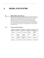
Model 8703 System
19
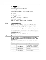
4.1.2
I/O Connector Terminal Functions (Connectors J100 & J101)
Connector Terminal
Name
Description
J100
1
GROUND
Power return
2
12 VOLTS
Input power, 10–12 V
J101
1
ANALOG IN–
Voltage-controlled rate input. Connect to analog
common.
Note:
This is connected to the ANALOG IN- of the
8712 module.
2
ANALOG
IN+
Voltage-controlled rate input. Connecting to analog
voltage ±10 V gives full-scale rate of 2 kHz. The input
impedance is 14.1 k
Ω
to ground. Note: This is
connected to the ANALOG IN+ of the 8712 module.
3
OPTO RET
Opto-coupler return. Connect to digital ground close to
control logic.
4
DIR/A
Opto-coupled TTL control input defined by MODE 0,1
inputs. In Step/Direction mode, controls direction:
high=clockwise, low=counterclockwise. In Quadrature
mode, acts as quadrature A.
5
PULSE/B
Opto-coupled TTL control input defined by MODE0,1
inputs. In Step/Direction mode, each falling edge
initiates a step. In Quadrature mode, acts as
quadrature B.
6
LIDLE
Opto-coupled TTL input. Low input disables pulse
generation and reduces power consumption. Can also
be used as system interlock.
7
LFAULT
Open-collector opto-coupler output pulled low when
output amplifier temperature limit is exceeded. On start-
up, firmware version number is present on this pin in
the form of on/off pulses.
8
TEMP+
Voltage proportional to the output-amplifier case
temperature. A voltage greater than 4 V (at 80 ºC) pulls
LFAULT low. A voltage greater than 4.12 V (at 85 ºC)
turns the output off. The output is turned on if the
voltage decreases to 3.86 V (at 75 ºC).
9
TEMP
RETURN
Ground reference for terminal 11. Do not tie to
GROUND (terminal 1).
4.1.3
Setting the Control Mode
Set the Model 8703 control mode using the DIP switches located at S100.
These switches control the MODE0 and MODE1 driver inputs.
Содержание New Focus 8703
Страница 1: ...Model 8712 Picomotor Driver Model 8703 System Driver User s Manual Single Axis Picomotor Driver ...
Страница 10: ......
Страница 34: ...24 Model 8703 System 4 3 Model 8703 System Board Layout System Board Upper Layer Top View ...
Страница 35: ...Model 8703 System 25 System Board Bottom Layer Top View Dimensions of Model 8703 ...


